background image

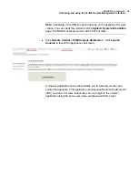
Note:

Availability of the HTML5 option depends on the appliance firmware

version. You can check the version from the

System

>

System Information

page. The BIOS must show version 00.01.0016 or later.

Click

Remote Control

>

KVM/Console Redirection

. Click

Launch

Console

to launch the appliance shell menu.

A JViewer application opens that enables you to remotely monitor and
control the appliance. This application requires Java Runtime Environment
(JRE) version 6.0 or later. Install Java. You can login to the JViewer
application using the same user name and password from step

3

34

Installation procedures

Accessing and using the Veritas Remote Management interface

Содержание 5150

Страница 1: ...Veritas 5150 Appliance Hardware Installation Guide ...

Страница 2: ...uthorization of Veritas Technologies LLC and its licensors if any THE DOCUMENTATION IS PROVIDED AS IS AND ALL EXPRESS OR IMPLIED CONDITIONS REPRESENTATIONS AND WARRANTIES INCLUDING ANY IMPLIED WARRANTY OF MERCHANTABILITY FITNESS FOR A PARTICULAR PURPOSE OR NON INFRINGEMENT ARE DISCLAIMED EXCEPT TO THE EXTENT THAT SUCH DISCLAIMERS ARE HELD TO BE LEGALLY INVALID VERITAS TECHNOLOGIES LLC SHALL NOT BE...

Страница 3: ...ation is available on the Veritas website https www veritas com content support en_US dpp Appliances html Documentation feedback Your feedback is important to us Suggest improvements or report errors or omissions to the documentation Include the document title document version chapter title and section title of the text on which you are reporting Send feedback to APPL docs veritas com You can also...

Страница 4: ...ments 17 Customer provided environment and supplies 17 Appliance shipping container contents 18 Electrical and environmental requirements 18 Heat dissipation 18 Prerequisites for the Veritas Remote Management Interface configuration 19 Chapter 3 Installation procedures 21 Installing the appliance into a rack 22 Connecting the network cables 26 Connecting the power cords 26 Turning on the hardware ...

Страница 5: ...ion About the appliance The Veritas 5150 Appliance is a hardware and software storage system that can scale to 14 TB of usable capacity Figure 1 1 Veritas 5150 Appliance The Veritas 5150 Appliance supports the following software Flex version 1 3 and later Refer to the Veritas 5150 documentation at the following site for details about usable storage options Appliance Documentation 1 Chapter ...

Страница 6: ...guration Slot Boot OS Intel 2280 M 2 SATA SSD 480GB RAID 1 0 1 Internal storage SEAGATE 8TB SAS 12G 7 2K RPM 3 5 RAID 10 4 5 6 7 Certificate SMART 2280 M 2 SATA SSD 32GB N A N A Appliance control panel The front panel of the Veritas 5150 Appliance includes a small panel that is attached to the right side of the device The panel provides basic control of the system as well as LED status indicators ...

Страница 7: ...egrated ID LED and the blue server board LED on and off The system ID LED identifies the system for maintenance when it is racked with similar server systems System ID button with integrated LED The front control panel includes one LED for each of the 1 GB RJ45 port on the Quad Gigabit Ethernet OCP module When network links are detected on the controllers the LEDs are activated and remain solid gr...

Страница 8: ...the current health of the appliance Two locations are provided for you to monitor the health of the system You can find the first location on the front control panel while the second location is located on the back edge of the server board It is viewable from the rear of the appliance Both LEDs show the same state of health See About the System Status LED states on page 9 System Status LED The app...

Страница 9: ...or this feature The first location is on the Front Control Panel while the second location is on the back edge of the server board Table 1 4 System Status LED states Description Criticality State Color System power is off AC and or DC System is in EuP Lot6 Off Mode System is in S5 Soft Off State Not ready Off The system is not operating No color Indicates that the system is running in S0 State and...

Страница 10: ...il from power supply and Processor Thermal Control Therm Ctrl sensors Power supply predictive failure occurred while redundant power supply configuration was present Unable to use all of the installed memory more than one DIMM is installed Correctable errors over a threshold and migrating to a spare DIMM memory sparing This indicates that the system has no spared DIMMs a redundancy lost condition ...

Страница 11: ...drive HSC is offline or degraded Degraded The system is operating in a degraded state although still functional or The system is operating in a redundant state but with an impending failure warning 1 Hz blinking Green Non fatal although the system is likely to fail due to the following issues Critical threshold crossed Voltage temperature including HSBP temp input power to power supply output curr...

Страница 12: ... for this condition Both uBoot BMC FW images are bad Chassis ID shows blue solid on for this condition 240 VA fault Fatal error in processor initialization Processor family not identical Processor model not identical Processor core thread counts not identical Processor cache size not identical Unable to synchronize processor frequency Unable to synchronize QPI link frequency Uncorrectable memory e...

Страница 13: ... LED states The power supply module has a bi color LED to represent the current status of the power supply The following table provides a description of each power supply state Table 1 7 Power supply LED states Power supply condition LED Output on and ok Solid green No AC power to all power supplies Off AC is present but only 12 VSB or is in cold redundant state 1 Hz blinking green AC cord is unpl...

Страница 14: ...ower supply The following table provides a description of the SSD LED states Table 1 8 SSD LED states Power supply condition LED SSD is receiving power Solid green No power to the SSD Off Drive activities to the SSD are on going Blinking green Appliance rear panel The rear panel of the appliance contains several default ports that are embedded Figure 1 4 Rear panel The following list describes the...

Страница 15: ...n configure the IPMI sub system for your appliances You can use the remote management port located on the rear panel of the appliance to connect to the IPMI sub system The following figure shows the remote management port or the IPMI port on the rear panel of the appliance The IPMI is beneficial after an unexpected power outage shuts down the connected system In case the appliance is not accessibl...

Страница 16: ...ranch offices and remote data centers Access the appliance shell remotely using IPMI if regular network interface is not possible Note Only the appliance menu can be accessed by using the IPMI interface The web console cannot be accessed by using the IPMI interface Reimage the appliance from the IPMI interface by using ISO redirection Monitor hardware health of the appliance from a remote location...

Страница 17: ...ion the rack cabinet Should be at least 100 cm 4 feet from walls Should have at least 100 cm 4 feet from other cabinets on the front and back of the appliance Data centers with two foot spaces in the front and in the back of the appliances are acceptable with proper cooling and ventilation Refer to the following section for more details See Heat dissipation on page 18 The following describes the n...

Страница 18: ...nty and license information Safety Compliance flyer Rail installation card Two power cables Bezel Electrical and environmental requirements This section lists the electrical and environmental specifications for the Veritas 5150 Appliance Electrical requirements 100 127 V 10A 2 power cords at 50 60 Hz 200 240 V 5A 2 power cords at 50 60 Hz Environmental requirements 10 C to 35 C 50 F to 95 F Heat d...

Страница 19: ...d the cabinet rear or other air block Refer to the Veritas 5150 Appliance Product Description Guide for specifications about temperature and cooling Appliance documentation Prerequisites for the Veritas Remote Management Interface configuration Verify the following configuration prerequisites The remote management IPMI port auto negotiates its link speed to 1 Gbps Note If the Veritas Remote Manage...

Страница 20: ... a private internal network remember to configure the settings accordingly in your network address translation NAT The remote management IPMI port must be configured as a DHCP or static address 20 Preinstallation requirements Prerequisites for the Veritas Remote Management Interface configuration ...

Страница 21: ...cs Installing the appliance into a rack Connecting the network cables Connecting the power cords Turning on the hardware and verifying operation Configuring the Veritas Remote Management Interface Accessing and using the Veritas Remote Management interface 3 Chapter ...

Страница 22: ...Installing the appliance into a rack To install the appliance into the rack 1 Extend both of the rails until they lock in place 22 Installation procedures Installing the appliance into a rack ...

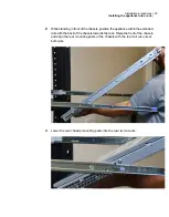
Страница 23: ... the back of the chassis towards the rack Raise the front of the chassis and align the rear mounting posts of the chassis with the rear rail cut outs of both rails 3 Lower the rear chassis mounting posts into the rear rail cut outs 23 Installation procedures Installing the appliance into a rack ...

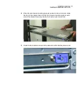
Страница 24: ... of the chassis down until the front chassis mounting posts on each side of the chassis fit securely into the front rail cut outs on each rail 5 Check the front rail locks on each of the rails and confirm that they are secured 24 Installation procedures Installing the appliance into a rack ...

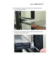
Страница 25: ...e rails and push the appliance into the rack as far as possible 7 Fasten the front of the appliance to the rack with the two captive fasteners that are attached to the front of the chassis 25 Installation procedures Installing the appliance into a rack ...

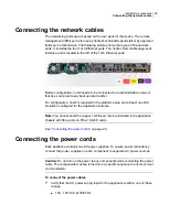
Страница 26: ...m setup and at least one NIC should be configured for the application instance Note You cannot bond the copper 1 GbE port that are installed in the appliance chassis with fibre ports on PCIe 10 GbE cards See Connecting the power cords on page 26 Connecting the power cords Each appliance contains two AC power supplies To ensure power redundancy connect the power supplies on each component to separa...

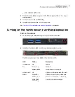
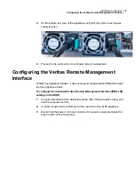
Страница 27: ...e press the Power button 2 Verify that the bottom LED in all the four disk drive slots are green The following table provides details of the disk drive LEDs Description States LED No fault Disk fault A RAID rebuild is in progress Off Solid amber Blinking amber 1 Status LED Top Power is on and the disk has spun down Power is on but there is no disk activity Power is on and the disk is spinning up C...

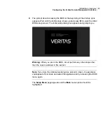
Страница 28: ...through the Flex Appliance Shell To configure the dedicated Veritas Remote Management Interface IPMI LAN settings in the BIOS 1 Connect a standard video cable between the VGA Video Graphics Array port and the computer monitor 2 Connect a keyboard to a USB port at the rear of the Flex 5150 appliance 3 Ensure that the power cords are connected to a power supply and press the power switch on the fron...

Страница 29: ...Warning When you are in the BIOS do not perform any other steps other than the ones mentioned in this section Note If you miss the initial setup dialog box prompt in step 4 the appliance shell appears Shut down and restart the appliance and try accessing the BIOS menu again The Setup Menu page appears and the Main menu option should be highlighted 29 Installation procedures Configuring the Veritas...

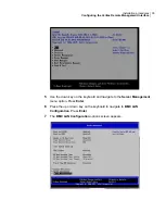
Страница 30: ...ver Management menu option Press Enter 6 Press the up or down key on the keyboard to navigate to BMC LAN Configuration Press Enter 7 The BMC LAN Configuration options screen appears 30 Installation procedures Configuring the Veritas Remote Management Interface ...

Страница 31: ...agement LAN Configuration option Use the information supplied by the customer to fill in the following fields IP Source IP address Subnet mask Gateway IP 31 Installation procedures Configuring the Veritas Remote Management Interface ...

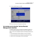
Страница 32: ...Veritas Remote Management interface to log on to the appliance shell Before you use the remote management interface the following prerequisites must be met The Remote Management interface IPMI port must first be configured At least one power cable must be connected to a functioning power source At least one user must be enabled to use the LAN channel s 32 Installation procedures Accessing and usin...

Страница 33: ...ars 3 Enter your login credentials The default user name is sysadmin The default password is P ssw0rd where 0 is the number zero Click Login 4 Click the Remote Control section located at the top of the page The Remote Control section lets you remotely monitor and control the server Do one of the following to launch the Flex Appliance Shell If available navigate to Remote Control iKVM over HTML5 Cl...

Страница 34: ... Redirection Click Launch Console to launch the appliance shell menu A JViewer application opens that enables you to remotely monitor and control the appliance This application requires Java Runtime Environment JRE version 6 0 or later Install Java You can login to the JViewer application using the same user name and password from step 3 34 Installation procedures Accessing and using the Veritas R...

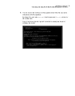
Страница 35: ...sword for the appliance By default the user name hostadmin has the password P ssw0rd where 0 is the number zero Type and then enter the system command to actually see the list of available commands 35 Installation procedures Accessing and using the Veritas Remote Management interface ...

Страница 36: ... 13 system status 9 rear panel 14 shipping contents 18 turning on hardware 27 B best practices heat dissipation 18 D documentation 16 H heat dissipation 18 I IP address eth0 NIC1 port 26 IPMI configuration about 15 O Open Me First container appliance 18 P prerequisites Veritas Remote Management Interface configuration 19 R rack cabinet requirements 17 V Veritas Remote Management Interface configur...

Отзывы: