Bx/U/2016
20/37 tel. (22) 751 95 50
www.venture.pl
fax. (22) 751 22 59
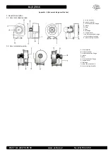
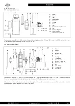
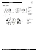
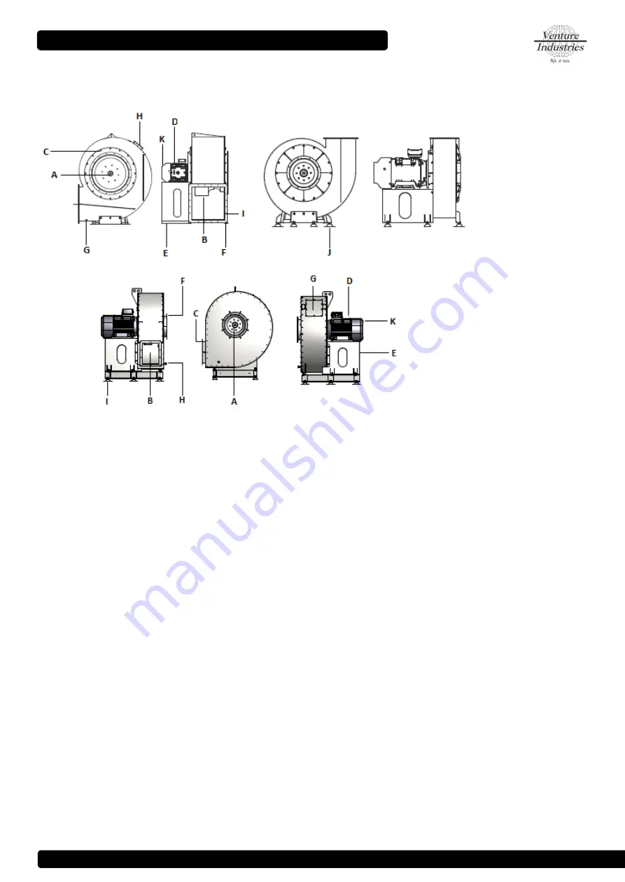
Appendix - A (Schematic diagram of the fan)
1. General description
1.1. Fans in standard version
A – inlet, impeller
B – outlet, impeller
C – inlet connection flange
D - motor
E - base
F - foot
G - drainage
H – review cover
I – outlet connection flange
J – vibro-isolator (variant)
K - motor cooling impeller
1.2. Fans in isolated version
A - inlet, impeller
B - outlet, impeller
C - outlet connection flange
D - motor
E - base
F – inlet connection flange
G – review cover
H - drainage
I – vibro-isolator (variant)
K - motor cooling impeller


