


9
UNIT DESIGN
AND OPERATING
LOGIC
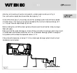
The unit operates as follows:
Warm stale extract air from the room flows to the unit, where it is filtered, then air flows
through the heat exchanger and is exhausted outside by the extract fan.
Clean cold air from outside is moved by the supply filter.
Then filtered air flows through the heat exchanger and is moved to the room with the
supply fan.
Heat energy of warm extract air is transferred to clean intake fresh air from outside and
warms it up.
The air flows remain fully separated within the heat exchanger.
Heat and energy recovery minimizes heat losses and ensure humidity balance, thus reducing
expenses for heating in the cold seasons and air conditioning in the warm season.
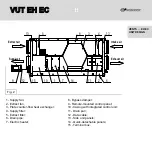
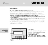
The unit is a frame structure consisting of six 25 mm thick rigidly fixed aluzinc sandwich panels,
internally filled with mineral wool for sound insulation.
The unit components: the quick detachable specially sealed service panels 14 provide
maintenance access; the side casing panels 13 with a terminal box 15 fixed to the outer
surface of one them.
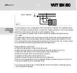
The terminal box incorporates a terminal block (not shown in Fig. 2) with the wires routed
from the circuit control board.
The sealed cable gland is used for routing of power and ground cables from the unit and
connection to the terminal block.
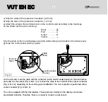
The wiring diagram for connection of the air handling unit is shown on inner side
of the terminal box lid.
VUT EH EC
VUT EH EC
Содержание VUT 300-1 EH EC
Страница 1: ...USER S MANUAL VUT EH EC VUT EH EC ...
Страница 40: ...V41EN 03 VUT EH EC VUT EH EC ...