


12
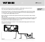
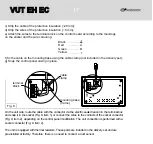
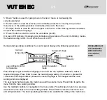
The unit is designed for ceiling mounting by means of the threaded rod fixed inside the
threaded dowel (Fig. 3). Optionally, it may be rigidly fixed on a horizontal even surface
(Fig. 4). Mount the unit to provide enough access for maintenance or repair operations.
For the minimum distances from the unit to the walls, refer to the Fig. 5.
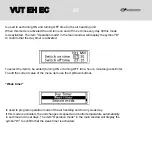
MOUNTING
AND SET-UP
To attain the best performance of the unit and to
minimise turbulence-induced air pressure losses
while mounting connect the straight air duct section
to the spigots on both sides of the unit.
Minimum straight air duct length:
equal to 1 air duct diameter on intake air spigot.
equal to 3 air duct diameter on supply air spigot.
Fig
. 5
Fig
. 3
Fig
.
4
The minimum distance for service access
to the unit
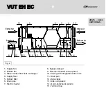
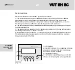
Location of electronic control unit
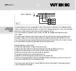
If the unit supply and exhaust spigots are not connected to air ducts, these must be covered
with a grille or with another protecting device with maximum mesh width 12.5 mm to prevent
free access to the unit fans.
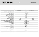
VUT EH EC
VUT EH EC
Содержание VUT 300-1 EH EC
Страница 1: ...USER S MANUAL VUT EH EC VUT EH EC ...
Страница 40: ...V41EN 03 VUT EH EC VUT EH EC ...