6
Micra 150 E
MOUNTINg AND SET-Up
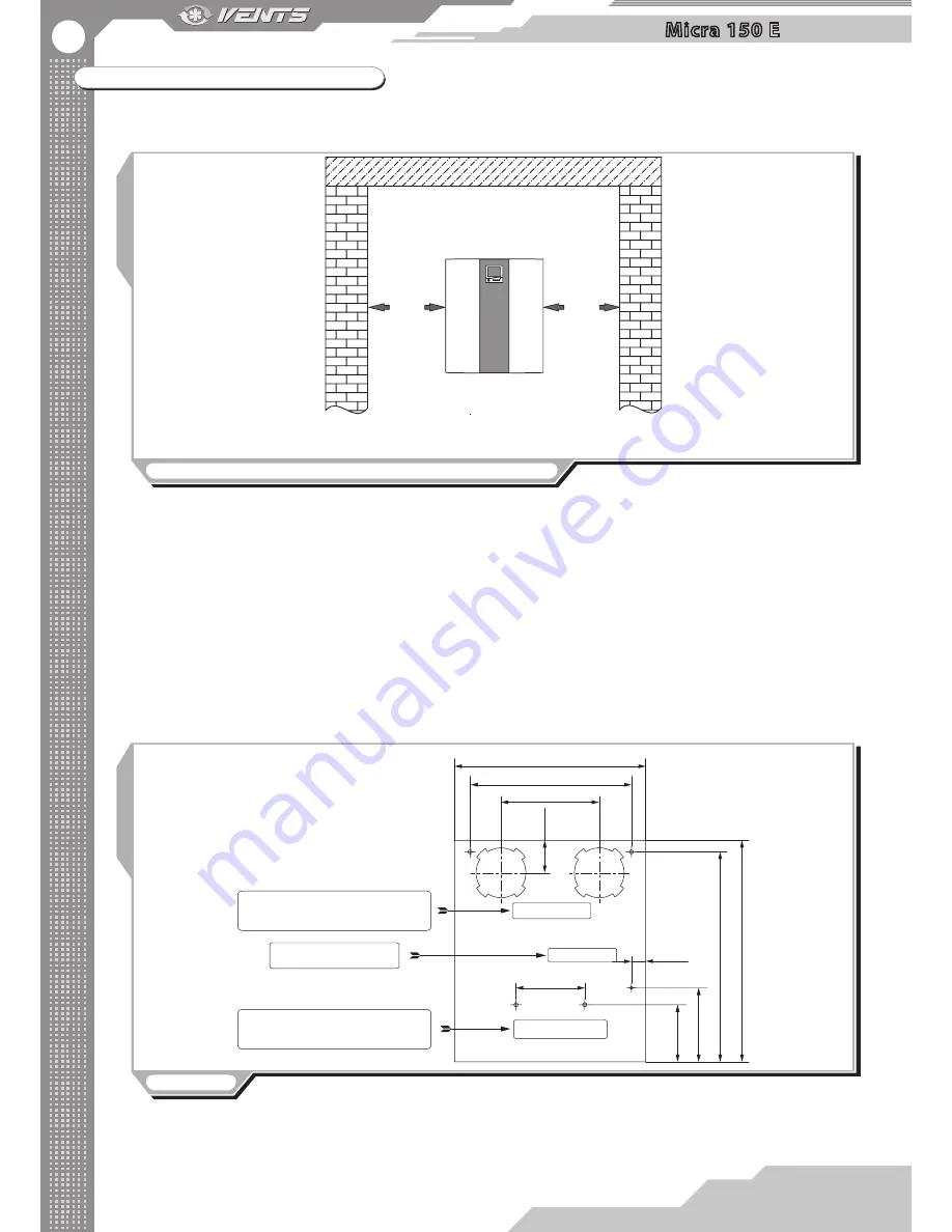
Mount the unit to provide enough access for maintenance or repair operations. The wall for mounting must have even surface. Any
surface irregularities will lead to unit casing skew and may prevent the unit from operating properly. The minimum distances from the
unit to the mounting surfaces are shown in fig. 3.
Fig. 3. Minimum distance from the unit to the surfaces
min 300 mm
min 300 mm
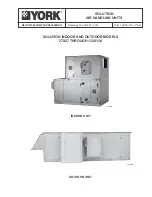
The unit is designed for installation directly in the premise to be ventilated. Prior to starting mounting operations mark and bore
holes in the wall with the master plate, fig. 4.
Mounting sequence with the master plate, fig. 5:
1. Fix the master plate on the wall with a self-adhesive tape at required level.
2. Indicate two marks for two holes Ø130 mm for air ducts and four holes Ø 8 mm for the unit fasteners.
3. Take off the master plate and drill through holes for the air ducts and holes, 90 mm deep for the unit fasteners. Insert the dowels,
remove the perforated fillers for the air ducts from the master plate and re-install the master plate back using a self-adhesive tape.
4. Insert the air ducts into the respective openings in the master plate.
5. Fill the spaces between the air ducts and the wall with a mounting foam through the specially designed holes in the master plate.
Wait till a mounting foam hardens (solidification time depends on the foam mark), take off the master plate and remove the foam excess.
Cut off the protruding air duct parts to be flush with the wall surface.
6. Insert the unit spigots to the air ducts.
7. Open the access door in the unit and remove the heat exchanger.
8. Mount the unit to the wall with the countersunk head screws and 8x80 dowels (included into delivery set) into two Ø 8 mm holes.
9. Install the heat exchanger and close the access door.
10. Fix the outer ventilation box (not included into delivery set) or Ø 125 mm ventilation grille on the outer wall of the building.
Fig. 4 Master plate
2 holes for Ø 125 mm air duct.
Fill the gaps between the wall and the air
ducts with a mounting foam.
2 holes for Ø 125 mm air duct.
Fill the gaps between the wall and the air
ducts with a mounting foam.
Drill 4 holes with Ø 8 tool for 90 mm deep
as per master plate.
Drill 4 holes with Ø 8 tool for 90 mm deep
as per master plate.
Point for cable rounding
inside the unit.
Point for cable rounding
inside the unit.
497
420
255
38,5
180
85
145
190
545
575
Содержание Micra 150 E
Страница 1: ...User Manual Micra 150 E Air handling unit with heat recovery ...
Страница 17: ...2013 V73 1EN 04 ...


