


Tires
1. Always maintain the proper tire pressure to achieve optimum traction, ride, and tire life.
Front tire: 16 x 7.5 x 8 - maximum recommended inflation is 24 PSI.
Rear tire: 15 x 4.0 x 8 - maximum recommended inflation is 40 PSI. Minimum inflation is 20
PSI.
Grease Locations
1. Grease both rear wheels, the two drive wheel bearings, and the steering pivot. (1 pump
each) Refer to page D-2. Do not over grease.
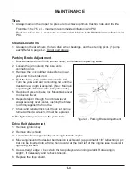
Parking Brake Adjustment
1. Block wheels so the VR300 cannot move, and release the parking brake.
2. Loosen the jam nuts on the yoke ends
connecting rod.
3. Remove the lock nut that connects the lower
yoke end to the brake rod.
4. Pull the lower yoke end from the brake rod.
Turn the yoke end and connecting rod until the
desired new length is acquired. (Note: Maintain
equal length of threads into both yoke ends.)
5. Reconnect yoke to brake rod. Move brake lever
to observe travel.
6. Repeat steps 3 through 5 until brake lever
snaps securely over center, pushing the brake
rod firmly against the front tire.
7. Check and reinstall lock nut. If lock nut can be
turned without a wrench, it must be replaced.
8. Re-tighten the jam nuts on the yoke ends.
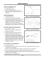
Drive Belt Adjustment
1. Remove ignition key.
2. Remove drive shield.
3. Loosen the four engine bolts just enough to slide engine.
4. Move engine until the desired belt tension is achieved. (approximatelt 1/8” deflection) A pry
bar can be inserted into a frame hole located at the front left of the engine base to assist in
tightening the belt.
5. Use a straight edge to be certain the two pulleys are running parallel. Rotate engine
slightly, if necessary, and recheck tension.
6. Replace the drive shield.
MAINTENANCE
D-4
Fig ure 9 - Parking Brake Adjustment
Содержание VR300
Страница 7: ...Safety Decal Locations SAFETY B 3 ...
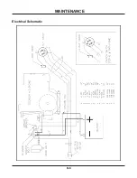
Страница 19: ...Electrical Schematic MAINTENANCE D 6 ...
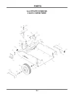
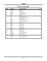
Страница 20: ...PARTS E 1 ILLUSTRATED DRAWING CHAIR COMPARTMENT ...
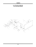
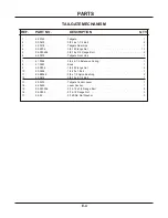
Страница 22: ...PARTS E 3 ILLUSTRATED DRAWING TAILGATE MECHANISM ...
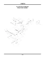
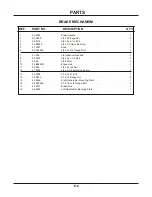
Страница 24: ...PARTS E 5 ILLUSTRATED DRAWING BRAKE MECHANISM ...
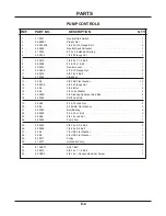
Страница 26: ...PARTS E 7 ILLUSTRATED DRAWING PUMP CONTROLS ...
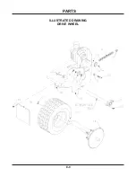
Страница 28: ...PARTS E 9 ILLUSTRATED DRAWING DRIVE WHEEL ...
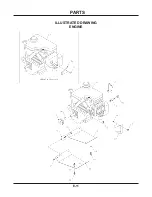
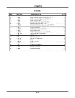
Страница 30: ...PARTS E 11 ILLUSTRATED DRAWING ENGINE ...
Страница 32: ...PARTS E 13 ILLUSTRATED DRAWING HANDLE BAR CONTROLS ...
Страница 34: ...PARTS E 15 ILLUSTRATED DRAWING COAST LEVER ELECTRICAL PARTS ...
Страница 36: ...PARTS E 17 ILLUSTRATED DRAWING SHIELDS BATTERY ...
Страница 38: ...PARTS F 1 ILLUSTRATED DRAWING GUN RACK ...
Страница 40: ...PARTS F 3 ILLUSTRATED DRAWING BRAKE LEVER EXTENSION ...
Страница 42: ...PARTS F 5 ILLUSTRATED DRAWING RAMP TAILGATE LEVER EXTENSION ...
Страница 44: ...PARTS F 7 ILLUSTRATED DRAWING TACHOMETER HOUR METER ...