Operation - 16
GENERAL OPERATION
GENERAL OPERATION
* Refer to power unit operator’s manual for operation of
power unit controls.
Daily Inspection
1.
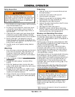
Always set the parking brake, shut off power
unit engine, remove the ignition key, and ensure
all moving parts have come to a complete stop
before inspecting components, or attempting
any repair or adjustment.
Park machine on a level surface, with the engine
shut off and all fluids cold.
2. Perform a visual inspection of both the power
unit and the mower deck. Look for loose or
missing hardware, damaged components, or
signs of wear.
3. Inspect the drive belts and mower blades. Belts
should be in good condition. Blades should be
sharp and securely fastened. Service as required.
4. Refer to the power unit operator’s manual.
Check the power unit’s engine oil, hydraulic oil,
cooling system, tire pressure, and fuel level. Add
fluid or service as required.
5. Test the power unit’s operator safety interlock
system*.
Attaching
1. Drive the power unit slowly forward into the hitch
arms of the mower deck. Align the lift arms of
the power unit with the mower hitch arms by
raising or lowering the front hitch and complete
the engagement.
2. Once completely engaged, close the front hitch
locking lever.*
3. Engage the parking brake* and shut off the
engine.
4. Place the attachment belt onto the PTO drive
pulley on the power unit. Ensure the belt is prop-
erly seated in each pulley.
5. Engage the main belt tensioner. NOTE: if deck
is raised to the top position, the deck shield will
interfere with the belt tensioner.
6. Always check to ensure the deck belt is properly
located in each pulley groove before attempting
to operate.
Detaching
1. Park the power unit on a level surface and set
the parking brake.*
2. Lower the mower deck to the ground.
3. Shut off power unit engine.
4. Raise the mower deck to the highest cutting
height position for easy reattachment.
5. Disengage the main belt tensioner.
6. Remove the attachment belt from the PTO drive
pulley of the power unit.
7. Disengage the hitch locking lever.*
8. Restart the power unit and slowly back away
from the mower. A side to side movement of the
steering wheel may aid disengagement.
Mowing and Operating Procedure
Before operation, perform daily inspection and con-
firm that the cutting height is set properly. Set the
power unit’s weight transfer system* (if equipped) to
the desired setting.
With the power unit engine running between 2,000
and 2,500 RPM, engage the PTO switch. Adjust the
throttle to the desired engine RPM.
Lower the mower deck to the ground and place
the power unit’s primary S.D.L.A. control lever in
the float position by pushing it to the right until the
detent engages. The lever will stay in this position
until intentionally removed.
Begin forward motion in the desired path of mowing.
Avoid obstacles, removing debris as necessary.
A stripe pattern in the grass is produced when each
mowing pass is done in the opposite direction of
the pass beside it. This look is enhanced by the
full length roller, which helps to roll the grass in the
direction of travel.
Lift the mower deck when the edge of the mowing
area is reached. Turn the power unit and mower
around and align for the next pass.
Always shut off the engine, remove the ignition
key, and set the parking brake before checking
mower deck or blade condition, or attempting
any repair or adjustment.
Blades should be kept in good condition. Sharp
blades will increase efficiency and improve the
quality of cut.
Содержание LM600
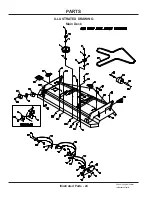
Страница 24: ...Illustrated Parts 24 Use only original Ventrac replacement parts ILLUSTRATED DRAWING Main Deck PARTS ...
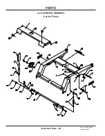
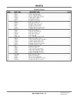
Страница 26: ...PARTS Illustrated Parts 26 Use only original Ventrac replacement parts ILLUSTRATED DRAWING Carrier Frame ...
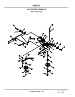
Страница 30: ...PARTS Illustrated Parts 30 Use only original Ventrac replacement parts ILLUSTRATED DRAWING Hitch Assembly ...
Страница 32: ...PARTS Illustrated Parts 32 Use only original Ventrac replacement parts ILLUSTRATED DRAWING Spindles Blades ...

