Vent-Axia Lo-Carbon Responce Series Скачать руководство пользователя страница 7

Display modes 

When first powered on, the display will run through an initialisation 
sequence and then activate prism mode (cover on). 
When a button is pressed, the display will go into the menu system and 
display as viewed without the prism.  
The display will return to prism mode after 30 seconds of inactivity (i.e. 
no button presses). 
When activating the menu, the initial button push will not change any 
settings. 
Prism mode may also be re-activated by holding the pull-cord for 5 
seconds (if applicable).  
 

Prism Mode 

When the controller is in ‘prism mode’ the display will be mirrored such 
that the characters are shown correctly when viewed through the prism 
fitted in the fan cover. 
When activated, prism mode will run for 15 minutes, first showing the 
day logger then cycling between displaying: 
 

  Airflow rate (Pro models only, other models display speed setting) 

  Estimated duct pressure (Pro models only) 

  Current RH% (HT models only) 

 
Calibration process will run after the first 15 minutes (if CV / F-2 mode 
enabled); see Advanced settings for further details. 
 

Menu  

If the buttons are pressed the display goes from prism mode to direct 
view mode and menu activated. If the buttons are not pressed for 30 
seconds the display reverts to prism mode. 
 
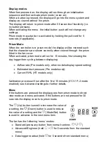
The   (Up) button is used to increase the value of 
a setting, the   (Down) button is used to reduce 
the value of a setting and the   (Mode/Set) button 
is used to advance to the next menu item.  
 
The fan has the following ‘menu’ modes: 

  Standard (press any button from normal runtime -       ) 


Advanced/Engineer 

(hold  

+  

for 5 seconds from the standard 

menu) 

  Data-logger readout (hold   for 5 seconds from standard menu) 

Содержание Lo-Carbon Responce Series

Страница 1: ...tructions Stock Ref N 494143 Response 7 494144 Response 7 Pro 494150 Response 7 SELV 494149 Response 7 Pro SELV PLEASE READ INSTRUCTIONS IN CONJUNCTION WITH ILLUSTRATIONS PLEASE SAVE THESE INSTRUCTION...

Страница 2: ......

Страница 3: ...installation within Zones 1 2 C The Fan should be provided with a local isolator switch capable of disconnecting all poles having a contact separation of at least 3mm D Ensure that the mains supply V...

Страница 4: ...the fan to suit its installation The display is also used to show the day logger and power run meter The fan can be wall window or panel ceiling mounted ACCESSORIES not supplied WALL FITTING KIT A ran...

Страница 5: ...lace the front panel EXTERIOR WALL MOUNTING 1 For wall mounting cut a 117mm diameter hole through the wall and insert the wall sleeve Slope the sleeve slightly downwards away from the fan Where necess...

Страница 6: ...enclosed or covered with insulation The fan is a class ll double insulated product and MUST NOT be earthed 1 Select and follow the appropriate wiring diagram Fig 1 2 3 or 4 5 6 2 Check all connection...

Страница 7: ...ll run for 15 minutes first showing the day logger then cycling between displaying Airflow rate Pro models only other models display speed setting Estimated duct pressure Pro models only Current RH HT...

Страница 8: ...c n normal LS overrun c Y comfort mode c n unl Enable disable lock code loc lock code enabled unl lock code disabled unlocked unl Menu lock code Up down selects current digit X moves to next digit 10c...

Страница 9: ...d rise function to detect rapid rises in humidity when the ambient rH is under the threshold setting If a rapid rise is detected the fan will increase in speed proportionally between the trickle and b...

Страница 10: ...errun duration of 5 minutes will take place This will override LS comfort mode boosting the fan immediately An activation when a Pullcord LS Light Switch boost is already active shall cancel overrun t...

Страница 11: ...press of the Mode button will return the fan to the commissioning menu D SERVICING AND MAINTENANCE WARNING THE FAN AND ANCILLARY CONTROL EQUIPMENT MUST BE ISOLATED FROM THE POWER SUPPLY DURING MAINTE...

Страница 12: ...us boost 1 with no trickle facility The fan is internally fused Fig 3 Continuous trickle with boost facility The fan is internally fused Fig 1 Continuous trickle with boost via pull cord The fan is in...

Страница 13: ...facility SELV models Fig 6 Continuous trickle with boost facility via LS or internal pullcord SELV models Fig 4 Continuous trickle with pullcord boost SELV models N L 1 Phase Supply 220 240V 50Hz FUSE...

Страница 14: ...g the controls Pull front panel as shown Loosen screws DO NOT REMOVE FROM GRILLE the screws are self retaining Pull inner grille away from housing as shown Open up the internal cover to access the spi...

Страница 15: ......

Страница 16: ...oduct rating label attached to the unit Has not been subjected to misuse neglect or damage Has not been modified or repaired by any person not authorised by the company IF CLAIMING UNDER TERMS OF GUAR...

Отзывы: