Page 8
Specifications are subject to change without notice.
Installation Instructions
Distributed by Simx Limited
[email protected] | www.manrose.co.nz
Installation Instructions
Specifications are subject to change without notice.
Page 9
[email protected] | www.manrose.co.nz
Distributed by Simx Limited
MultiVent Continuous Extract Ventilation
MultiVent Continuous Extract Ventilation
FEATURE DESCRIPTIONS
Comfort Mode
If Comfort mode is enabled the unit will behave as follows to all LS inputs
The above applies to all LS inputs. The times are not adjustable by the user.
Delay On
A delay can be set so that the unit will not respond to an input until after the set delay has elapsed, applies to LS inputs only.
Overrun Timer
The unit can be set to run for a defined period after the input is removed, applies to LS inputs only.
Humidity – Rapid rise*
Rapid Rise humidity response functions to detect rapid rises in humidity when the ambient %RH is under the threshold setting.
If a rapid rise is detected the fan will boost until the humidity lowers again.
Humidity – Ambient response*
When ambient response is enabled the threshold set point is modified based on the ambient temperature.
This helps to prevent nuisance boosting of the unit as temperatures changes during the day.
Humidity – Threshold*
The unit will boost when the RH is above the threshold set point.
Analogue inputs
Both analogue inputs have adjustable low and high trigger voltages within the 0-10V range.
The response to being above or below either of the threshold voltages is user settable.
Note: The display doesn’t show a decimal point, for example at threshold voltage of 5.2V, is displayed as “52” on the unit.
Digital Inputs
The unit can be set to change speed (selectable), based on whether the digital inputs are above or below the threshold voltage.
See the table of Low Voltage Connections for details.
Display Lock
To protect the settings on the MultiVent unit a pin code can be enabled via the main menu.
Once the lock function has been enabled the Pin code can be set. The 3-digit pin is A to F, 0 to 9, and the
default is LoC
.
Trigger
Action
LS input active less than 5 minutes
No action (continue to run at Normal speed)
LS input active more than 5 minutes but less
than 20 minutes
Once LS input is removed, fan will run at user selected speed for the length
of time LS was present plus the set over-run time (if over run is enabled).
LS input active more the 20 minutes
Unit will Boost after 20mins.
Once LS input is removed, fan will run at user selected speed for 20 minutes
plus the set overrun time (if over run is enabled).
UNIT ADJUSTMENT
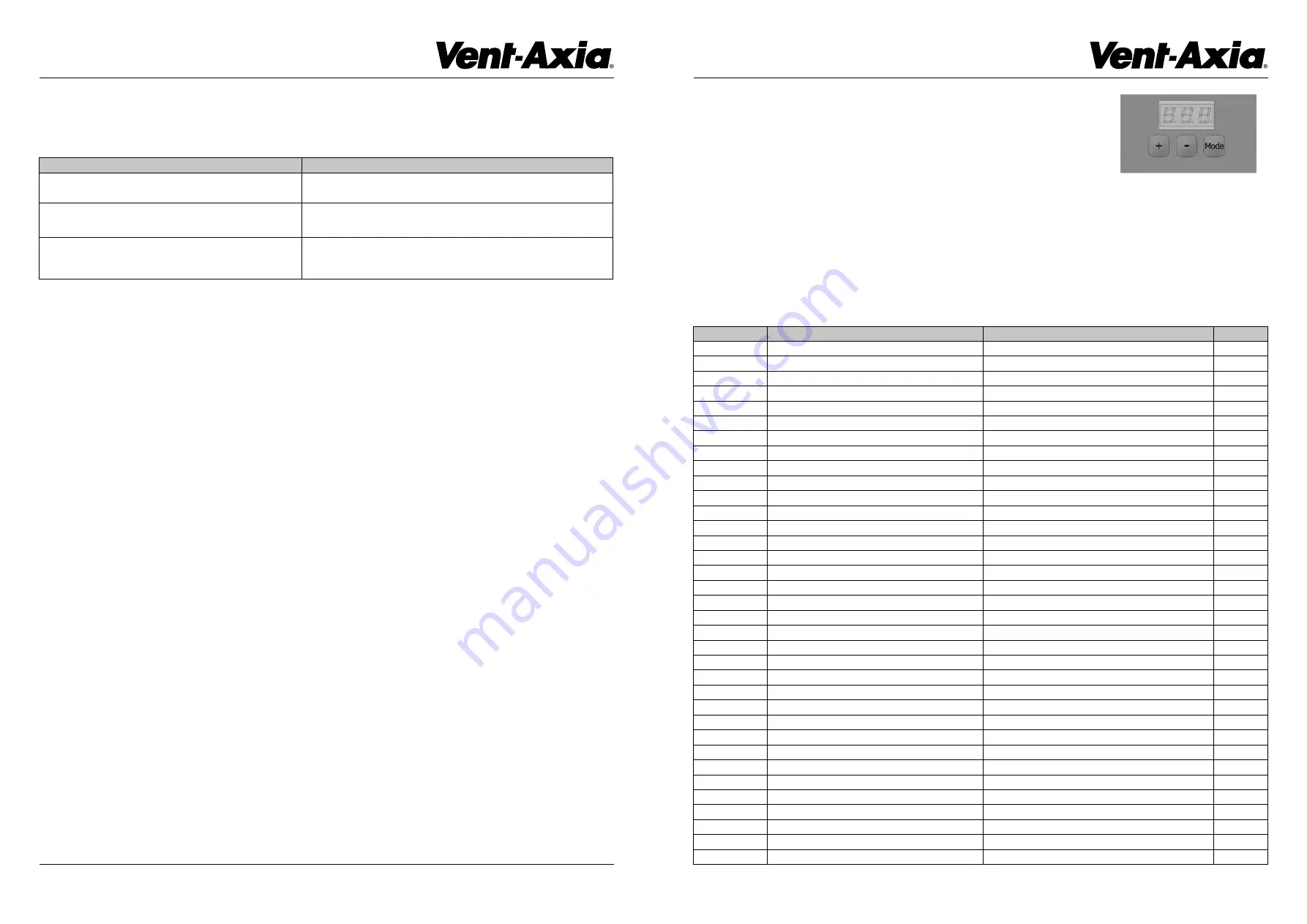
1. Commissioning and configuration on all products is supported by the 3 digit user interface
and associated push buttons.
2. When powered on, the unit will display the firmware revision number, after a few seconds the unit
will display the first option in the menu structure (see below).
3. The display will enter standby mode after 30 seconds, press the Mode button to turn the display back on.
4. Changes to the settings can be made via the
+
and
–
buttons, the Mode button will accept changes and move onto the next menu option.
5. When setting the speeds, there is an internal logic: Low<Normal<Boost<Purge. I.e., Boost is always higher than Normal.
6. The actions for each of the Live Switched (LS), inputs are selectable. The setting for delays and over run timers are applicable to all inputs.
7. To restore factory settings, Press and hold “Mode” button for 10 seconds.
Display Text
Function
Selections
Default
L10
Low Speed
1 to 97% motor speed
10%
n35
Normal Speed
2 to 98% motor speed
35%
b70
Boost Speed
3 to 99% motor speed
70%
P100
Purge Speed
4 to 100% motor speed
100%
LS1
Live Switch 1
Low, boost or purge speed
Low
LS2
Live Switch 2
Low, boost or purge speed
Boost
LS3
Live Switch 1 & 2
Low, boost or purge speed
Purge
c-n
Comfort Mode
Comfort mode - Yes or No
No
d-n
Delay On
Delay on - Yes or No
No
d10
Delay On Time
Delay to boost duration - 1 to 60 minutes
10m
o-n
Overrun
Overrun - Yes or No
No
o10
Overrun Time
Overrun duration - 1 to 60 minutes
10m
r-y
Humidity - Rapid Rise
Rapid Rise Rapid rise - Yes or No
Yes
A-n
Humidity - Ambient Response
Ambient response - Yes or No
No
h70
Humidity - Ambient Response Threshold
Ambient response threshold - 40 to 80% RH
70%
C2b
CO2 - Boost Threshold
Boost threshold 650 - 4950 PPM
950
C2P
CO2 - Purge Threshold
Purge threshold 700 - 5000 PPM
2000
A1LA
Analogue 1 - Low Action
Low, normal, boost or purge speed
Low
A1HA
Analogue 1 - High Action
Low, normal, boost or purge speed
Boost
A1tL
Analogue 1 - Low Threshold
Low threshold - 1 - 99
15
A1tH
Analogue 1 - High Threshold
High threshold - 1 - 99
75
A2LA
Analogue 2 - Low Action
Low, normal, boost or purge speed
Low
A2HA
Analogue 2 - High Action
Low, normal, boost or purge speed
Boost
A2tL
Analogue 2 - Low Threshold
Low threshold - 1 - 99
15
A2tH
Analogue 2 - High Threshold
High threshold - 1 - 99
75
D1
Digital input 1 - Action
Low, boost or purge speed
Low
D2
Digital input 2 - Action
Low, boost or purge speed
Boost
unl
Unlock Code
Turn the menu lock OFF/ON
PIn
Display Pin
3 characters A to 9
LoC
dt30
Display Time
Adjust display illumination period
30 s
rot
Rotate Display
Invert the display
rot
hu
Humidity
Show the current internal humidity
%
tu
Temperature
Show the current internal temperature
°C
CO2
CO2
Show the current CO2 level
PPM
end
End
End of menu (loop to start)
USER CONFIGURABLE PARAMETERS


