background image

HDL-64E S3


High Definition LiDAR Sensor


Page 54


Velodyne LiDAR, Inc. 

©

2019


63-HDL64ES3 REV K 


Velodyne LiDAR, Inc. 

345 Digital Drive


Morgan Hill, CA 95037


408.465.2800 voice


408.779.9227 fax


408.779.9208 service fax


www.velodynelidar.com


Service E mail: [email protected] 

Product E mail: [email protected] 

Technical E mail: [email protected]


Sales E mail: 

 [email protected]


All Velodyne products are made in the U.S.A. 


Specifications subject to change without notice. 

Other trademarks or registered trademarks are 
property of their respective owner. 


63-HDL64ES3 

Rev K DEC 2017 

Содержание HDL-64E S3

Страница 1: ...USER S MANUAL AND PROGRAMMING GUIDE HDL 64E S3 High Definition LiDAR Sensor ...

Страница 2: ...hange Spin Rate in Flash Memory 14 Change Spin Rate in RAM Only 14 Limit Horizontal FOV Data Collected 14 Define Sensor Memory IP Source and Destination Addresses 15 Dual Returns 15 Laser Output Power Level Management and Reporting 17 Noise Level Adjustment 17 Upload Calibration Data 18 External GPS Time Synchronization 18 Packet Format and Status Byte for GPS Time Stamping 19 Timestamp Accuracy R...

Страница 3: ...atus Bits 38 CRC Checksum Algorithm 39 Last Six Bytes Examples 39 Appendix F Dual Two Point Calibration Methodology Code Samples 43 Coordinate Calculation Algorithm Sample Code 43 Intensity Compensation vs Distance 45 Calibration Window 45 Intensity Value Corrected by Distance 46 Appendix G Ethernet Timing Tables 47 Sensor Ethernet Transmit Timing Tables 47 How to Use the Timing Tables 47 Laser an...

Страница 4: ...n point symbol is intended to alert the user to the presence of important operating and maintenance servicing instructions in the literature accompanying the product 1 Read Instructions All safety and operating instructions should be read before the product is operated 2 Retain Instructions The safety and operating instructions should be retained for future reference 3 Heed Warnings All warnings o...

Страница 5: ...al This manual and programming guide covers Installation and wiring The data packet format The serial Interface Software updates GPS Viewing the data Programming information HDL 64E S3 Lower Laser Block Upper Laser Block Vertical Field of View VFOV Primary Application 32 lasers separated by 1 2 o vertical spacing 32 lasers separated by 1 3 o vertical spacing 2 to 24 8 Autonomous navigation For the...

Страница 6: ...ta intensive point cloud than a rotating mirror design The sensor delivers a 360 o horizontal Field of View HFOV and a 26 8 o vertical FOV Additionally state of the art digital signal processing and waveform analysis are employed to provide high accuracy extended distance sensing and intensity data The sensor is rated to provide usable returns up to 120 meters The sensor employs a direct drive mot...

Страница 7: ...9 63 HDL64ES3 REV K 360 Spinning Lidar Sensor 26 8 Valid Data Range 0 9 m to 120 m 3 to 394 Uncalibrated Point Cloud Data Packets Calibrated Point Cloud Data as 3D image Digital Sensor Recorder and Viewer Software XML Laser Calibration File Figure 2 LiDAR System Overview ...

Страница 8: ...e sensor is weatherproofed to withstand wind rain and other adverse weather conditions The spinning nature of the sensor helps it shed excess water from the front window that could hamper performance Wiring Cables are not provided The end user needs to fabricate cables with the mating connectors to those on the sensor Refer to the wiring diagram in Appendix B Power THE SENSOR IS RATED FOR 10 32 VO...

Страница 9: ...these fundamental steps 1 Establish communication with the sensor 2 Create a calibration table either from the calibration data included in stream from the sensor or from the included xml data file 3 Parse the packets for rotation block distance and intensity data 4 Apply the calibration factors to the data 5 Plot or store the data as needed The following provides more detail on each of the above ...

Страница 10: ...lasers horizOffsetCorrection cm The horizontal offset of each laser as viewed from the back of the laser Fixed positive or negative value for all lasers Maximum Intensity Value from 0 to 255 Usually 255 Minimum Intensity Value from 0 to 255 Usually 0 Focal Distance cm Maximum intensity distance Focal Slope The control intensity amount The calibration table once assembled contains 64 instances of t...

Страница 11: ...x F NOTE The minimum return distance for the sensor is approximately 3 feet 0 9 meters Ignore returns closer than this NOTE A file on the CD called HDL Source Example shows the calculations using the above correction factors This DSR uses this code to determine 3D locations of sensor data points 5 Plot or store the data as needed For DSR the point cloud data once determined is plotted onscreen The...

Страница 12: ...he spin rate command store data in the sensor s flash memory Data stored in flash memory through serial commands is retained during firmware updates or power cycles The sensor has no echo back feature so no serial data is returned from the sensor Commands can be sent using a terminal program or by using batch files e g bat A sample bat file is shown below Sample Batch File bat MODE COM3 9600 N 8 1...

Страница 13: ...grees sss is an integer between 000 and 360 nnn ending angle in degrees nnn is an ineger between 000 and 360 HDLRETS Strongest return only this is the default setting HDLRETB Both strongest and last returns If the strongest return is equal to the last return the next strongest return is reported HDLRETL Last return only HDLPWRA0 Set auto power for all lasers with return of 8 bit laser raw intensit...

Страница 14: ...multiple sensors controlled by a closed loop application you can adjust the sensors spin rates without storing the new RPM in flash memory this preserves flash memory over time To control the sensor s spin rate in RAM only issue a serial command of the case sensitive format HDLRPNnnnn where nnnn is an integer between 0300 and 1200 The sensor immediately unit adopts the new spin rate You shouldn t ...

Страница 15: ...dresses Dual Returns Different environmental conditions require a different priority of the type of distance point returns Hence you can define which distance points strongest last or both have the return priority This feature is also known as dual returns The packet structure remains unchanged regardless of the option selected Strongest This is the normal case Last Poor visibility conditions such...

Страница 16: ...le A box is 5 meters from the sensor The laser partially hits the box and gets the strongest signal Another box is 20 meters from the sensor The laser partially hits the second box and generates the last return The sensor is not moving so the returns generate circle patterns Both Strongest and Last Returns Only Strongest Return Only Last Return NOTE The X Y Z and distance figures at the bottom of ...

Страница 17: ...aser normalized intensity level and no laser power output Serial Command for Laser Output Power Distance Data Low Byte Intensity Data Byte HDLPWRA0 Reports Distance Power 0 7 Intensity raw data 0 255 Bit 8 7 6 5 4 3 2 1 8 7 6 5 4 3 2 1 HDLPWRFn8 Reports Distance Power 0 7 Intensity raw data 0 255 Bit 8 7 6 5 4 3 2 1 8 7 6 5 4 3 2 1 HDLPWRA8 Reports Distance Intensity data normalized by calibration...

Страница 18: ...icular packet is reported in the form of microseconds since the top of the hour and from that time each subsequent laser s firing time can be derived via the table published in Appendix H and included on the CD Calculating the exact firing time requires a GPS receiver generating a sync pulse and the GPRMC NMEA record over a dedicated RS 232 serial port The output from the GPS receiver is connected...

Страница 19: ... synch and GPS command have signal V Only GPS command signal no PPS synch P Only PPS synch signal no GPS time command Timestamp Accuracy Rules and Accuracy The following rules and subsequent accuracy apply for GPS timestamps GPS Connection Timestamp Info Accuracy Notes GPS isn t connected GPS Status 0 The sensor starts running on its own clock starting at midnight Jan 1 2000 This date and time dat...

Страница 20: ...ple laser 32 fires simultaneously with laser 0 laser 33 fires with laser 1 and so on The sensor has an equal number of upper and lower block returns Hence when interpreting the delay table each sequential pair of data blocks represents the upper and lower block respectively Each upper and lower block data pair in the Ethernet packet has the same delay value Six firings of each block takes 139 µs a...

Страница 21: ... the firmware update 1 Obtain the update file from Velodyne 2 Connect the wiring harness RS 232 cable to a standard Windows compatible PC or laptop serial port 3 Power up the sensor 4 Execute the update file the screen below appears Figure 3 HDL Software Update Screen 5 Select the appropriate COM Port 6 Click Update 7 The firmware is uploaded and check summed before it is applied to the flash memo...

Страница 22: ...HDL 64E S3 High Definition LiDAR Sensor Page 22 Velodyne LiDAR Inc 2019 63 HDL64ES3 REV K Appendix A Mechanical Drawings Figure 4 Top View Figure 5 Rear Unit View ...

Страница 23: ...HDL 64E S3 High Definition LiDAR Sensor Page 23 Velodyne LiDAR Inc 2019 63 HDL64ES3 REV K Figure 6 Side and Front Unit View Figure 7 Bottom Unit View ...

Страница 24: ...HDL 64E S3 High Definition LiDAR Sensor Page 24 Velodyne LiDAR Inc 2019 63 HDL64ES3 REV K Figure 8 Mounting Surface Example ...

Страница 25: ... GPS Serial optional NMEA message from GPS 7 Black Serial RX Control messages from user s computer 8 Red Serial Ground All data inputs PPS GPS Serial and Serial RX are considered active in the logical 1 state Logical 1 Voltage must be greater than 2 V and no more than 25 V Logical 0 Voltage must be less than 1 3 V Ethernet Connector The Ethernet connection is used for output of data only but requi...

Страница 26: ...l file provided with the sensor contains correction factors for the proper alignment of the point cloud information gathered for each laser When implemented properly the image viewable from the DSR is calibrated to provide an accurate visual representation of the environment in which the sensor is being used Also use these calibration factors and equations in any program using the data generated b...

Страница 27: ... after the session has been aborted NOTE An Ethernet capture utility such as Wireshark can also be used as a pcap capture utility Playback Recorded Files 1 Use the File Open command to open a previously captured pcap file for playback The DSR playback controls are similar to any DVD VCR control features 2 Press the Play button to render the file The Play button toggles to a Pause button when in pl...

Страница 28: ...Axis Rotation Y Rotate CW Shift Y Rotate CCW X Shift Y Shift L Left H Right U Up D Down X Axis Rotation P Rotate CW Shift P Rotate CCW Y Axis Rotation R Rotate CW Shift R Rotate CCW Aux Functions Ctrl Z Y P R F B L H U D Direction Fine Movement Alt Z Y P R F B L H U D Direction Very Fine Movement DSR Mouse Controls Rotational Left Button Move Z Shift F Forward B Back Slide Right Button Move Zoom S...

Страница 29: ... i 1 64 7 LaserId i temp 1 Add high and low bytes of Vertical Correction Factor together and check if positive or negative correction factor VerticalCorr i temp 3 256 temp 2 if VerticalCorr i 32768 VerticalCorr i VerticalCorr i 65536 End Scale Vertical Correction Factor by Dividing by 100 VerticalCorr i VerticalCorr i 100 Add high and low bytes of Rotational Correction Factor together and check if...

Страница 30: ...single value s 46 single value s 45 256 Fov end single value s 44 single value s 43 256 warning value s 13 power value s 12 Humidity value s 58 Done with Unit Parameters Calibration and Sensor Parameter Data Laser ID is a 1 byte integer Most of the output calibration data are 2 byte signed integers except minimum and maximum intensity which use 1 byte each See Appendix E for more information Statu...

Страница 31: ...ity data is collected first followed by the lower block laser data The data packet is then combined with status and header data in a UDP packet transmitted over Ethernet The status data always contains a GPS 4 byte timestamp representing microseconds from the top of the hour In addition the status data contains one type of data The other status data rotates through a sequence of different pieces o...

Страница 32: ...GPS 54 84 T Temperature C 56 86 V Firmware Version 31 49 1 Status Type Calibration Unit Parameters refer to table later in this appendix 32 50 2 33 51 3 34 52 4 35 53 5 36 54 6 37 55 7 Status Value Example for Status Types of H M S D N Y G T and V Status Value Example Hex ASCII 15 21 21 Hours 9pm 38 19 19 Minutes 37 55 55 Seconds 0F 15 15th day of the Month 0C 12 12th Month December 0A 10 2010 50 ...

Страница 33: ...ation and Unit Parameters The last two bytes for status type and status value in the packet rotate to output the sensor information including time GPS status temperature firmware calibration data and sensor setting parameter etc Status type H M S D N Y G T and V output once every 16 packets one cycle Calibration data and sensor setting parameters are loaded from the flash memory when the sensor is...

Страница 34: ...al Correction High Byte 6 Far Distance Correction Low Bye 2 Byte Signed Integer 10 for cm 7 Far Distance Correction High Byte Cycle 3 1 Distance Correction X Low Byte 2 Byte Signed Integer 10 for cm 2 Distance Correction X High Byte 3 Distance Correction VLow Byte 2 Byte Signed Integer 10 for cm 4 Distance Correction VHigh Byte 5 Vertical Offset Correction Low Byte 2 Byte Signed Integer 10 for cm ...

Страница 35: ...gh Byte Cycle 7 1 Distance Correction X Low Byte 2 Byte Signed Integer 0 for cm 2 Distance Correction X High Byte 3 Distance Correction VLow Byte 2 Byte Signed Integer 10 for cm 4 Distance Correction VHigh Byte 5 Vertical Offset Correction Low Byte 2 Byte Signed Integer 10 for cm 6 Vertical Offset Correction High Byte 7 Horizontal Offset Correction Low Byte 2 Byte Signed Integer 10 for cm Cycle 8 ...

Страница 36: ...yte 2 Byte Signed Integer 10 for cm 4 Distance Correction YHigh Byte 5 Vertical Offset Correction Low Byte 2 Byte Signed Integer 10 for cm 6 Vertical Offset Correction High Byte 7 Horizontal Offset Correction Low Byte 2 Byte Signed Integer 10 for cm Cycle 256 1 Horizontal Offset Correction High Byte 2 Focal Distance Low Byte 2 Byte Signed Integer 10 for cm 3 Focal Distance High Byte 4 Focal Slope ...

Страница 37: ...me Low Byte 2 Byte Integer Hour Cycle 259 1 Real Life Time High Byte 2 IP Source 1 12 Digit String 3 IP Source 2 12 Digit String 4 IP Source 3 12 Digit String 5 IP Source 4 12 Digit String 6 IP Destination 1 12 Digit String 7 IP Destination 2 12 Digit String Cycle 260 1 IP Destination 3 12 Digit String 2 IP Destination 4 12 Digit String F9 Multiple Return Status 0 Strongest 1 Last 2 Both 4 Reserve...

Страница 38: ...a Packets per Laser x of Lasers 65 x 64 4160 about 1 per second Includes All Parameter Data Sets Warning Status Bits Bit Description Value Definitions 1 Lens Contamination 1 Clean Laser Lens 0 Laser Lens Doesn t Need Cleaning 2 Unit Too Hot Internally 1 Internal Temp 58 C 0 Not Over Temp 3 Unit Too Cold Internally 1 Internal Temp 5 C 0 Not Under Temp 4 5 6 PPS Signal 1 PPS Signal Present 0 No PPS ...

Страница 39: ...9b 0x04 0xf4 0x04 0xb7 0x00 0xCe 0x00 0x19 0x2e 0xe0 0x00 0x14 0x14 0xff CRC CA6C unsigned char TestDATA1 16 23 59 123 2 255 0 4 23 23 90 132 145 200 CRC 0x6328 unsigned char TestDATA2 0xf1 0x0b 0xf0 0x24 0x78 CRC 0x9411 unsigned char TestDATA3 0x06 0x07 main unsigned sh0rt remainder 0 f0r int byte 0 byte size0f TestDATA byte remainder A TestDATA byte 8 f0r unsigned char bit 8 bit 0 bit if remaind...

Страница 40: ...HDL 64E S3 High Definition LiDAR Sensor Page 40 Velodyne LiDAR Inc 2019 63 HDL64ES3 REV K ...

Страница 41: ...HDL 64E S3 High Definition LiDAR Sensor Page 41 Velodyne LiDAR Inc 2019 63 HDL64ES3 REV K ...

Страница 42: ...HDL 64E S3 High Definition LiDAR Sensor Page 42 Velodyne LiDAR Inc 2019 63 HDL64ES3 REV K ...

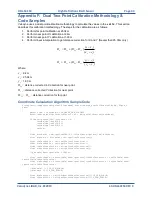
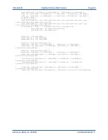
Страница 43: ...ulation Algorithm Sample Code firingData computeCoords guintl6 laserNum boost shared_ptr CalibrationDB db GLpos_t pos guintl6 idx laserNum VLS_LASER_PER_FIRING boost shared_ptr CalibrationPoint cal db getCalibration laserNum if data points idx distance 0 coords idx setX 0 0 coords idx setY 0 0 coords idx setZ 0 0 return float distancel db getDistLSB float data points idx distance float distance di...

Страница 44: ...orrection distanceCorrY distanceCorrX distancel VLS_DIM_SCALE distanceCorrX VLS_DIM_SCALE distanceCorrY VLS_DIM_SCALE distance distancel distanceCorrX xyDistance distance cosVertAngle vOffsetCorr sinVertAngle coords idx setX xyDistance sinRotAngle hOffsetCorr cosRotAngle pos getX VLS_DIM_SCALE distance distancel distanceCorrY xyDistance distance cosVertAngle vOffsetCorr sinVertAngle coords idx set...

Страница 45: ...is slope getting from cal data Intensity gets to max at focaldistance for different channel and it s from cal data too Calibration Window New intensity parameter added in calibration window focal distance At this distance intensity gets to max The focal distance is different from laser to laser On the upper block it averages 1500cm On the lower block it averages 800cm focal slope Controls intensit...

Страница 46: ...i intensity Get firing i distance here unit is 2mm float distance it getPoint i distance Calculate offset according calibration float focaloffset 256 l db getFocalDistance laser l3l00 l db getFocalDistance laser l3l00 get slope from calibration float focalslope db getFocalSlope laser Calculate corrected intensity vs distance float intensityVal1 intensityVal focalslope abs focaloffset 256 l distanc...

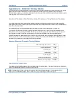
Страница 47: ...equal number of upper and lower block returns This is why when interpreting the delay table each sequential pair of data blocks represents the upper and lower block respectively and each upper and lower block pair of data blocks in the Ethernet packet has the same delay value Ethernet packets are assembled until the entire 1200 bytes have been collected representing six upper block sequences and s...

Страница 48: ...39 5 36 34 7 33 5 32 3 11 Upper 57 6 56 3 55 1 53 9 50 4 49 1 47 9 46 7 43 2 41 9 40 7 39 5 36 34 7 33 5 32 3 12 Lower 57 6 56 3 55 1 53 9 50 4 49 1 47 9 46 7 43 2 41 9 40 7 39 5 36 34 7 33 5 32 3 Data Block Laser Block Laser Number 16 31 and 48 63 Upper Lower 16 48 17 49 18 50 19 51 20 52 21 53 22 54 23 55 24 56 25 57 26 58 27 59 28 60 29 61 30 62 31 63 1 Upper 144 142 7 141 5 140 3 136 8 135 5 1...

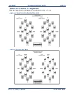
Страница 49: ... Sensor Page 49 Velodyne LiDAR Inc 2019 63 HDL64ES3 REV K Laser and Detector Arrangement The images below show the arrangement of the lasers and detectors in the unit Lasers as Seen from the Back of the Unit Laser as Seen on the Wall ...

Страница 50: ...c 2019 63 HDL64ES3 REV K Appendix I Angular Resolution RPM RPS Hz Total Laser Points per Revolution Points Per Laser per Revolution Angular Resolution degrees 0300 5 266 627 4167 0 0864 0600 10 133 333 2083 0 1728 0900 15 88 889 1389 0 2592 1200 20 66 657 1042 0 3456 ...

Страница 51: ...lution Unit doesn t spin Verify power connection and polarity Verify proper voltage should be 24 volts drawing about 3 5 to 4 amps Unit spins but no data Verify Ethernet wiring Verify packet output with another tool e g Ethereal Wireshark No serial communication Verify RS 232 connection Unit must be active and spinning for RS 232 update It may take several tries for the update to be effective ...

Страница 52: ...pendix K Service and Maintenance No service or maintenance requirements or procedures exist for the sensors However Velodyne does offer a preventative maintenance service for a fee For service maintenance please contact Velodyne at 408 465 2800 or log on to our website at www velodynelidar com ...

Страница 53: ... Specifications Sensor specifications including environmental and regulatory Specifications have been moved to product data sheets section of the Velodyne LiDAR website at this address www velodynelidar com For additional information contact Velodyne LiDAR Sales at www velododynelidar com contacts php ...

Страница 54: ... 779 9208 service fax www velodynelidar com Service E mail lidarservice velodyne com Product E mail help velodyne com Technical E mail lidarhelp velodyne com Sales E mail lidar velodyne com All Velodyne products are made in the U S A Specifications subject to change without notice Other trademarks or registered trademarks are property of their respective owner 63 HDL64ES3 Rev K DEC 2017 ...

Отзывы: