__________________________________________________________________________________________________________________________________________________________
21
POWER TRANSFORMER
N BLUE
L BROWN
6.3VAC
GRAY
RED
RED
YELLOW
YELLOW
BLACK
BROWN
BLUE
ORANGE
ZD043
OUTPUT TRANSFORMER
0
8
4
6.3VAC
GREEN
GND
R
GND
L
OUTPUT TRANSFORMER
8D002
8
0
4
ZD043
L
R
MAINS
EARTH
VIOLET
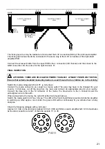
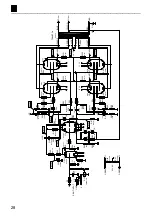
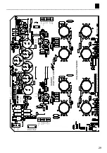
The thick grey wires may be twisted and connected the 6.3V connection (SK3) of the left-hand amplifier.
The thick green wires should be connected in the same way to the 6.3V connection of the right-hand
amplifier PCB.
Connect the screened cable from the input PCB to the L connection (left channel) and the screen to the
GND connection. Do the same for the right channel, R.
FINAL INSPECTION
!
ATTENTION: THERE ARE VOLTAGES OF MORE THAN 400V AT MANY POINTS ON THE PCB.
Ensure that suitable insulated measuring leads are used. Ensure that no children are in the vicinity.
Switch the mains voltage switch to OFF, ie. fully down.
Connect the mains connector via a lead to a mains outlet. The plug may have to be changed for your
country. In that case, cut off the plug from the lead, and connect an appropriate plug for your country.
Connect the blue wire to the N connector of the mains, the brown wire to the L connector and the
yellow/green wire to the earth.
When connected to the mains, the red LED at the front should light up.
Switch the mains switch to ON ie. fully up. The LED at the front should flicker green/red while the amplifier
is warming up. After approx. one minute, the green LED will be continuously lit, you will also hear a relay
energise.
Check the following voltages with a volt meter:
Approx. 6.3 VAC on the terminals marked 6.3 VAC (SK3 and SK4) on each amplifier half. 6.3V should also
be found at connectors 2 and 7 of the tube sockets, V1 to V8.
2
1
7
1
7
2
FIG 11


