


_______________________________________________________________________________________________________________________________________________________
20
◊
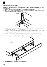
Mount the supply transformer in the middle of the cabinet. Ensure that the leads are positioned as
shown in the figure 6. The thick grey and green wires must be at the highest point.
◊
Mount an output transformer along the right-hand side of the housing, see figure 6. Check the po-
sition of the wires.
◊
Solder the transformer leads to the output terminals, see figure 7. Do not forget to slide a 3 cm
length of insulating heat shrink sleeve over the wires:
◊
Solder the double yellow wire to the 4 Ohm loudspeaker terminal.
Solder to the red wire to the 0 loudspeaker terminal.
Solder the blue wire to the 8 Ohm loudspeaker terminal.
IMPORTANT: Heat the terminals until the solder melts easily. Then slide the insulating heat
shrink sleeve over the leads.
!
IMPORTANT:
Ensure that the transformers do not touch any metal parts such as the loudspeaker
terminals or the input connector.
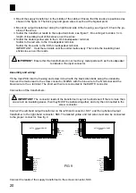
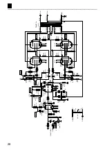
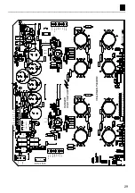
Assembly and wiring:
Fit the main PCB into the housing and screw it down with the black Allen bolts along the underside.
Connect the mains lead to the screw connector, MAINS, with the blue wire to the N terminal and the
brown wire to the L terminal. The short earth wire is connected to the EARTH connector.
Connection of the transformers:
!
IMPORTANT:
The connector leads of the transformer may not be shortened. If there is more than
one wire in an insulating sleeve, then they MUST be soldered together, and only then connected to the
screw connector.
Connect the left-hand output transformer to the left-hand connector, SK7, and the right-hand output
transformer to the right-hand connector, SK8. The twisted yellow and red wires must also be connected
to the proper connector. See fig. 9
GREEN
VIOLET
YELLOW LS+
BROWN
BLACK
BLACK
RED LS-
ORANGE
OUTPUT TRANSFORMER
ZD043
YELLOW
RED
BLUE
8
4
0
BROWN
ORANGE
RED LS-
BLACK
BLACK
GREEN
VIOLET
YELLOW LS+
ZD043
OUTPUT TRANSFORMER
BLUE
RED
YELLOW
8 0 4
FIG 9
Connect the leads of the supply transformer to the screw connector, SK6.


