CTC1000KP
V. 01 – 12/06/2013
7
©Velleman nv
2.
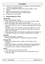
Using the 2 mounting holes as a template, mark off the positions
in the most appropriate place.
3.
Insert the included wall plugs if fixing into plaster or brick
surface.
4.
Attach the keypad using the included screws.
Make sure the tamper switch touches the wall.
5.
Put back the 2 cover plates.
9.
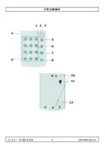
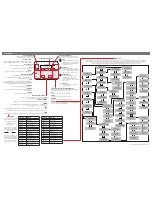
Understanding the LEDs
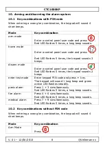
Green LED
The green LED indicates activity.
Green LED always on: the system is in normal operation mode.
Green LED flashes: the system is in test mode.
When the keypad is idle, all leds are off. After any key press, the
green active LED turns on for 5 seconds indicating that the keypad
is active.
The green LED will turn off after successful completion of a valid
keystroke sequence or when the pause in between key stokes is
longer than 5 seconds.
When the green LED turns off before a valid keystroke sequence is
completed (5 seconds), the previous entered keys are cleared.
Red LED
The green LED indicates connection.
The red LED flashes twice: the signal has been transmitted.
Orange LED
Orange LED flashes 5 times: battery is low (flashes during
operation).
Orange LED always on: tamper is triggered (on during operation).
When tamper alert and low battery are triggered together, the
orange LED turns is always on (during operation).
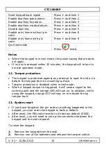
Notes
A short beep sounds with each key press.
If the user enters an invalid keystrok, the keypad will sound 4
continuous beeps.
Содержание CTC1000KP
Страница 2: ...CTC1000KP V 01 12 06 2013 2 Velleman nv ...


