background image


_______________________________________________________________________________________________________________________________________________________ 


16

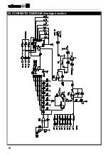
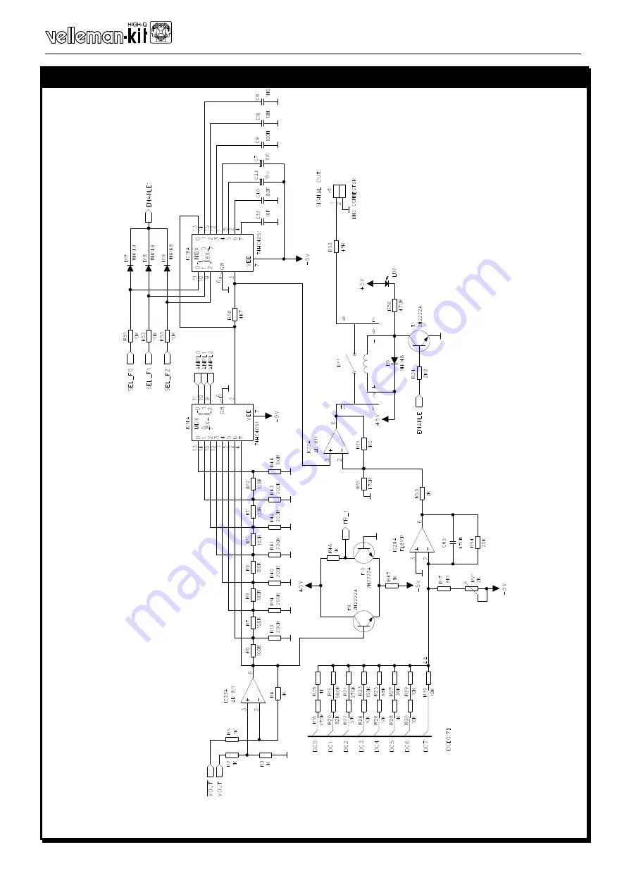
20. SCHEMATIC DIAGRAM: Analogue section. 


Содержание K8016

Страница 1: ...can create your own waveforms with the integrated signal wave editor Can be chained with Velleman PC oscilloscopes to the same PC printer port LPT1 2 or 3 Specifications Power supply Standard 12V DC a...

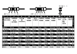
Страница 2: ...2 3 Aranciato Laranja Naranjado Oranssi Orange Orange Orange Orange Orange Orange Oranje 3 4 Giallo Amarelo Amarillo Keltainen Gul Gul Gul Gelb Yellow Jaune Geel 4 5 Verde Verde Verde Vihre Gr n Gr n...

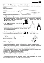
Страница 3: ...y when cutting excess leads hold the lead so they can not fly towards the eyes Needle nose pliers for bending leads or to hold components in place Small blade and phillips screwdrivers A basic range i...

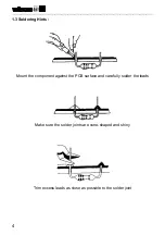
Страница 4: ...______________________________________________________________________ 4 1 3 Soldering Hints Mount the component against the PCB surface and carefully solder the leads Make sure the solder joints are...

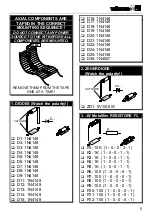
Страница 5: ...4148 q D3 1N4148 q D4 1N4148 q D5 1N4148 q D6 1N4148 q D7 1N4148 q D8 1N4148 q D9 1N4148 q D11 1N4148 q D12 1N4148 q D13 1N4148 q D14 1N4148 q D15 1N4148 q D16 1N4148 q D17 1N4148 q D18 1N4148 q D19 1...

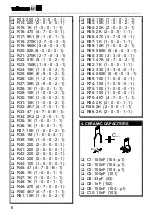
Страница 6: ...0 0 2 1 q R38 1M 1 0 0 4 1 q R39 10K 1 0 0 2 1 q R40 200 2 0 0 0 1 q R41 200 2 0 0 0 1 q R42 200 2 0 0 0 1 q R43 200 2 0 0 0 1 q R44 100 1 0 0 0 1 q R45 47 4 7 0 B 1 q R46 1K 1 0 0 1 1 q R47 1K 1 0 0...

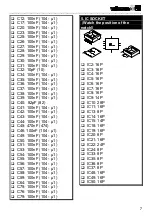
Страница 7: ...82pF 82 q C41 100nF 104 1 q C42 100nF 104 1 q C43 100nF 104 1 q C44 100nF 104 1 q C45 470nF 474 q C46 100nF 104 1 q C49 100nF 104 1 q C50 100nF 104 1 q C51 100nF 104 1 q C53 100nF 104 1 q C54 100nF 1...

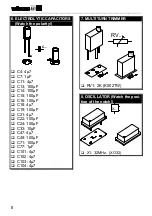
Страница 8: ...C CAPACITORS Watch the polarity C q C4 4 7 q C7 1 F q C11 4 7 q C13 100 F q C14 100 F q C15 100 F q C16 100 F q C18 4 7 q C19 100 F q C21 4 7 q C22 100 F q C24 100 F q C33 10 F q C47 4 7 q C48 100 F q...

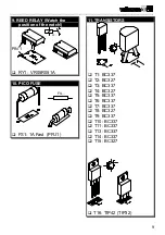
Страница 9: ...__________________________ 9 9 REED RELAY Watch the position of the notch PIN 1 1 RY q RY1 VR05R051A 10 PICO FUSE FS q FS1 1A Fast PFU1 11 TRANSISTORS q T1 BC337 q T2 BC327 q T3 BC337 q T4 BC327 q T5...

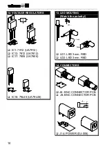
Страница 10: ...______________________________________ 10 12 VOLTAGE REGULATORS VR q IC1 7912 UA7912 q IC12 7812 UA7812 q IC17 7805 UA7805 q IC16 79L05 UA79L05 13 LED MOUTING Watch the polarity LD CATHODE 3mm q LD1 L...

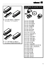
Страница 11: ...OM PRINTER PORT 15 IC Watch the position of the notch q IC2 74HC595 q IC3 74HC595 q IC4 74HC4518 q IC5 74HC595 q IC6 TDA8702 q IC7 74F161 q IC8 74HC162 q IC9 74HC14 q IC10 CY7C199 q IC11 74HC4518 q IC...

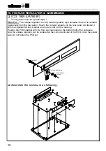
Страница 12: ...stic type because it has to be isolated galvanically from the rear panel Mount the voltage regulator on the rear panel and fasten it with the supplied M3 bolt washer and nut as shown on the drawing Po...

Страница 13: ...to 1000Hz 1KHz Adjust if necessary 1 Make sure the offset is set to 0V Adjust if necessary 6 Make sure the amplitude is set to 5Vpp Adjust if necessary 7 Select sinewave output 4 Readout 9 should now...

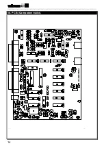
Страница 14: ..._______________________________________________________________________________________________________________________________________________________ 14 18 PCB Component side...

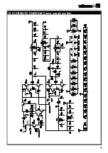
Страница 15: ...__________________________________________________________________________________________________________________________________________________________ 15 19 SCHEMATIC DIAGRAM Power supply section...

Страница 16: ..._______________________________________________________________________________________________________________________________________________________ 16 20 SCHEMATIC DIAGRAM Analogue section...

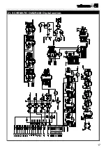
Страница 17: ...__________________________________________________________________________________________________________________________________________________________ 17 21 SCHEMATIC DIAGRAM Digital section...

Отзывы: