__________________________________________________________________________________________________________________________________________________________
13
17. CALIBRATION
To allow calibration, the unit must be connected to the computer and the
supplied software must be installed. Please consult the ‘Getting Started’
manual for details on the connection and installation procedure.
•
Select the function generator module [Function generator].
•
Select the correct parallel port [Options > Hardware setup].
•
Check if the ‘POWER ON’ (LD1) LED lights. If it does not light, check
the complete assembly and check the parallel port settings in the
•
options-hardware setup of the software.
•
Make sure the frequency is set to 1000Hz (1KHz).
Adjust if necessary (1).
•
Make sure the offset is set to 0V. Adjust if necessary (6).
•
Make sure the amplitude is set to 5Vpp. Adjust if necessary (7).
•
Select sinewave output (4). Readout (9) should now show a sine wave
and the ‘READY’ LED (LD2) should light.
•
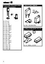
Connect a digital multimeter to the ‘signal out’ connector of the
generator. Set it to DC volts. Adjust the multi-turn trimmer RV1 until
the multimeter displays zero volts. If necessary, adjust the range of
the meter to obtain a higher resolution. Now you can check the wave-
form, using an oscilloscope or one of our PC- or handheld scopes
•
If for some the measured values are totally off, please inspect the
complete assembly, paying special attention to the solder joints, com-
ponent positioning and values.
•
If everything went well, you can fasten the PCB with the supplied
screws, and close the enclosure lid.
Your function generator is now ready for use !


