


- 19 -
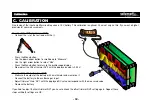
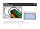
We have a nice waveform available at the test
pin, it is perfect for our measurements.
Turn off the scope, connect the red alligator
clip to the ‘test’-pin and turn on the scope.
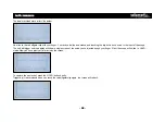
You should see something like this:
This is called a square wave. Note that the com-
plete waveform is drawn above the center of
the screen. This is because our waveform con-
tains not only an AC but also a DC component:
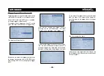
Now, enter the menu and select ‘
AC coupling
’
instead of ‘
AC+DC coupling
’
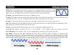
Now the position of the waveform changes, as
the DC component of the signal is blocked.
The scope only displays the AC part, which is
both positive and negative.
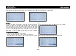
Let’s measure the
frequency
and
period
of
our waveform.
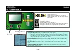
First, we turn on the markers, by pressing the
‘HOLD’-button. Next, we isolate a single period
of our waveform by moving both horizontal
markers as shown below:
The lower right hand corner displays the period
of our signal: 0.51ms. To display the frequency,
we select:
Now the scope will display the frequency of
our signal:
Note that there are also horizontal markers
available. They allow us to measure e.g. the
peak to peak value of our waveform, which is
also displayed in the lower right hand corner.
Let’s measure
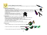
Displaying and measuring waveforms:
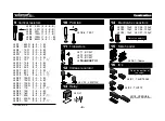
Содержание EDU08
Страница 2: ...Velleman N V Legen Heirweg 33 9890 Gavere Belgi...
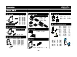
Страница 27: ...27 PCB BASE PCB...
Страница 28: ...28 PCB DISPLAY PCB...
Страница 29: ...29 PCB DISPLAY PCB...
Страница 30: ...30 Diagram...
Страница 32: ...Modifications and typographical errors reserved HEDU08 2013 ED1 Velleman nv Legen Heirweg 33 9890 Gavere Belgi...


