


Aqua-Hot™ Hydronic Heating System Owner’s Manual 07/04
Page 2
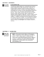
SECTION 1: OVERVIEW
Aqua-Hot
Overview,
continued
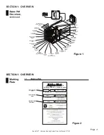
ELECTRONIC CONTROLLER
������ ���
R
t
o
H
d
l
o
C
Expansion
Tank
Circulation
Pump #3
Engine Preheat
Circulation
Pump
Diesel-Burner
Head
Engine Coolant
Supply
Hot Water
Outlet
(Domestic Water)
Diesel Fuel
Supply
Diesel Fuel
Return
Pressure-Relief
Valve
Cold Water
Inlet
(Domestic Water)
Engine
Coolant
Return
Diesel-Burner
Control
Unit
Mixer
Valve
Electric Heating
Element Access
Panel
Fill / Radiator
Cap
VAC Access
Panel
VAC Service
Input
Thermostat
Access Panel
Marking
Plates
Hour Meter
Heating Zones
Status
#5
#4
#3
#2
#1
Electric Heating
Element Status
Low Voltage
Reset
Low Tank-Level
Cutoff
Heating Status
Engine Preheat
Pump
Low Battery
Voltage Fault
Low Temp
Cutoff Status
Overload Fault
Pump #2
Pump #1
Pump #3
Diesel-Burner
Status
Motor Coach Heating Specialists
Electronic
Controller
Switch Panel
Circulation
Pump #2
Circulation
Pump #1
Heating Zones
Supply and Return
Ports
Boiler Tank
Drain Valve
Diesel
Electric
Engine
Preheat
������������������
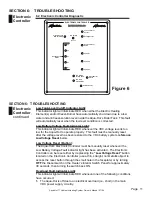
Figure 1
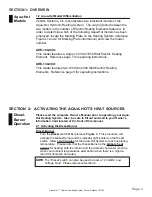
1.1
Marking Plate
Marking
Plate
AHE-100
02S
12 VDC / 170 Watts
Model Number
Diesel-Burner / DC Power
Serial Number
Electric Heating
Element / AC Power
Manufactured Date
Fuel Type / Firing Rate
02-637
120 VAC, 60 Hz / 1.65 kW
06-02
DIESEL / 50,000 BTU
R
Testing
Engineers
International
Listing No. 02L02
Complies with the requirements
of UL 307A
Made in U.S.A.
For Installation Only in Compartment Completely Closed Off from Living Quarters and Accessible
Only from the Outdoors.
Exhaust system MUST NOT terminate beneath the vehicle or under an openable window or vent.
Combustion Air MUST BE supplied from outside the vehicle.
CAUTION: This appliance operates on both AC and DC Electrical Power.
The AC Powered Electrical Heating Element can be wired using flexible nonmetallic cable (ROMEX).
USE COPPER CONDUCTORS ONLY
Use 25 Amp fuse for over current protection for DC Power Supply.
Use 20 Amp Circuit Breaker for over current protection for AC Power Supply.
Mount Heater near a Bay / Storage Door so Access Cover can be easily removed.
Minimum Heater clearances
Front (Decal Sides) - Open Access
Back - 0 inches
Top - 6 inches
Install in strict compliance with local codes, NFPA
501c and manufacturer’s instructions.
For additional product installation information visit www.aqua-hot.com or call 1-800-685-4298
�
By Vehicle Systems, Inc. Ft. Lupton, CO 80621
Manufactured
Date Box
Serial Number
Box
Model Number
Box
SECTION 1: OVERVIEW
Figure 2
SECTION 1: OVERVIEW