


Version 0.6
29 November 2004
Page 3 of 42
For use with Vega 100 E1 – SIP version 08.02.06 T007 or greater.
© 2002-2004 VegaStream Ltd.
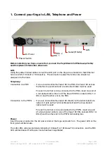
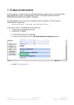
1. Connect your Vega to LAN, Telephone and Power
Serial (RS232)
LAN
DSL 2
DSL 1
Power Switch
AC Power
Before installing your Vega, ensure that you read the VegaStream VoIP Gateways Safety
and Compliance Information document.
LAN:
Using the yellow booted cable connect the LAN port on the Vega to a standard or fast Ethernet
hub or switch (10 baseT or 100 baseTx). The connector nearest the ferrite core should be
plugged into the Vega.
Telephony:
Connection to a PBX
- If you are connecting the Vega 100 to a PBX, the Vega 100 acts as
the NeTwork equipment and a red-booted cable must be used.
For each trunk that is to be connected to the PBX, insert one end of
a red booted cable into one of the Vega 100 DSL sockets [DSL 1 or
DSL 2] and the other end to the PBX.
Connection to the PSTN - If you are connecting the Vega 100 directly to the public telephone
network it acts as the Terminal Equipment and the blue-booted
cable must be used.
For each trunk that is to be connected to the PSTN, insert one end
of a blue booted cable to one of the Vega 100 DSL sockets [DSL1 or
DSL2] and the other end to the PSTN terminating box.
Power:
Insert the power cable into the AC power inlet on the Vega and switch on. The power LED on the
front panel will illuminate.
The LAN LEDs will also illuminate indicating 10 (baseT) or 100 (base TX) connection, and the FDX
LED will illuminate if Full Duplex mode has been negotiated.


