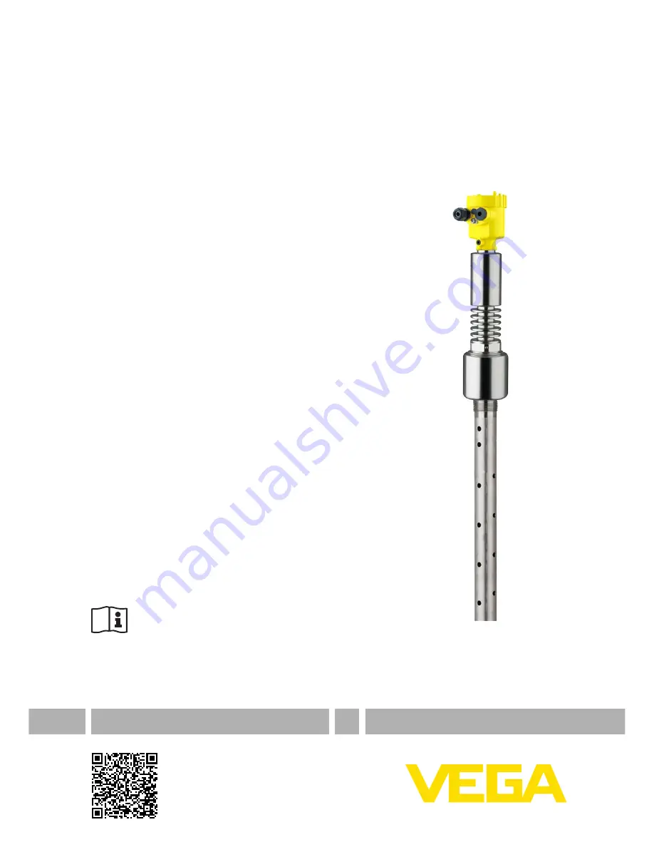
Quick setup guide
TDR sensor for continuous level and
interface measurement of liquids
VEGAFLEX 86
4 … 20 mA/HART - two-wireCoax probeWith SIL qualification-196 … +280 °C-196 … +450 °C
Document ID: 47615
Страница 1: ...Quick setup guide TDR sensor for continuous level and interface measurement of liquids VEGAFLEX 86 4 20 mA HART two wire Coax probe With SIL qualification 196 280 C 196 450 C Document ID 47615...
Страница 2: ...sing 9 4 3 Wiring plan double chamber housing 10 5 Set up with the display and adjustment module 5 1 Insert display and adjustment module 11 5 2 Parameter adjustment 12 6 Supplement 6 1 Technical data...
Страница 3: ...omplying with all prevailing regulations and guidelines The instrument must only be operated in a technically flawless and reliable condition The operator is responsible for the trouble free operation...
Страница 4: ...gle channel operation up to SIL2 The instrument can be used homogeneously redundant up to SIL3 in multi channel architecture with HFT 1 1 7 NAMUR recommendations NAMUR is the automation technology use...
Страница 5: ...Symbol of the device protection class 13 ID numbers instrument documentation 14 Reminder to observe the instrument documentation 15 Notified authority for CE marking 16 Approval directives 17 Marking...
Страница 6: ...4 20 mA HART two wire 47615 EN 150102 Download the smartphone app VEGA Tools from the Apple App Store or the Google Play Store Scan the Data Matrix code on the type label of the instrument or Enter th...
Страница 7: ...s in areas where high humidity is expected e g through cleaning processes Installations on cooled or heated vessels 3 2 Mounting instructions During operation the probe must not touch any installation...
Страница 8: ...ctronics To do this lift the terminal block with a small screwdriver and pull it out When reinserting the terminal block you should hear it snap in Proceed as follows 1 Unscrew the housing cover 2 If...
Страница 9: ...s released the terminal closes again You can find further information on the max wire cross section under Technical data Electromechanical data 7 Check the hold of the wires in the terminals by lightl...
Страница 10: ...uble chamber housing The following illustrations apply to the non Ex as well as to the Ex ia version 5 1 2 6 7 8 4 20mA Display 2 3 4 1 Fig 6 Terminal compartment double chamber housing 1 Voltage supp...
Страница 11: ...by 90 It is not necessary to interrupt the power supply Proceed as follows 1 Unscrew the housing cover 2 Place the display and adjustment module on the electronics in the desired position and turn it...
Страница 12: ...rameter adjustment 1 In this menu item you can select the application You can choose between level and interface measurement 2 In the menu item Medium Dielectric constant you can define the type of me...
Страница 13: ...a no measurement is possible 5 Lower dead band in this area no measurement is possible For this adjustment the distance is entered when the vessel is full and nearly empty If these values are not know...
Страница 14: ...Operating voltage Non Ex instrument Ex d instrument 9 6 35 V DC Ex ia instrument 9 6 30 V DC Ex d ia instrument 15 35 V DC Operating voltage with illuminated display and adjustment module Non Ex inst...
Страница 15: ...15 Notes VEGAFLEX 86 4 20 mA HART two wire 47615 EN 150102...
Страница 16: ...of delivery application practical use and operat ing conditions of the sensors and processing systems correspond to the information available at the time of printing Subject to change without prior n...