


35
6 Set up with the display and adjustment module
VEGABAR 83 • Modbus and Levelmaster protocol
46295-EN-131107
5. Save settings with
[OK]
and move with
[ESC]
and
[->]
to the max.
adjustment.
The min. adjustment is finished.
For an adjustment with filling, simply enter the actual measured value
indicated at the bottom of the display.
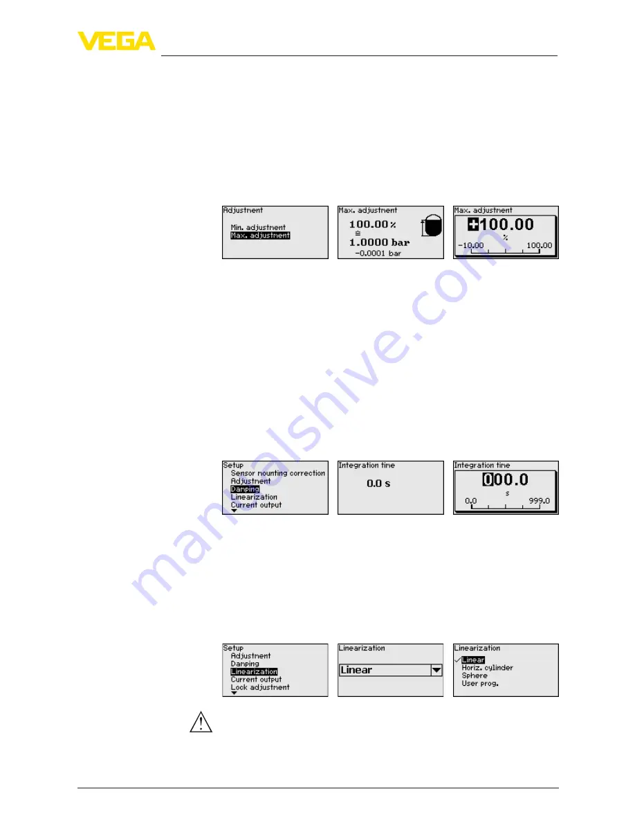
Proceed as follows:
1. Select with
[->]
the menu item "Max. adjustment" and confirm
with
[OK]
.
2. Edit the percentage value with
[OK]
and set the cursor to the
requested position with
[->]
.
3. Set the requested percentage value (e.g. 90 %) with
[+]
and save
with
[OK]
. The cursor jumps now to the pressure value.
4. Enter the pressure value for the full vessel (e.g. 900 mbar) cor-
responding to the percentage value.
5. Save settings with
[OK]
The max. adjustment is finished.
For an adjustment with filling, simply enter the actual measured value
indicated at the bottom of the display.
To damp process-dependent measured value fluctuations, set an
integration time of 0 … 999 s in this menu item. The increment is 0.1 s.
Depending on the sensor type, the factory setting is 0.1 s.
A linearization is necessary for all vessels in which the vessel volume
does not increase linearly with the level - e.g. a horizontal cylindri-
cal or spherical tank - and the indication or output of the volume is
required. Corresponding linearization curves are preprogrammed for
these vessels. They represent the correlation between the level per-
centage and vessel volume. The linearization applies to the measured
value indication and the current output.
Caution:
Note the following, if the respective sensor is used as part of an over-
fill protection system according to WHG:
If a linearization curve is selected, the measuring signal is no longer
necessarily linear to the filling height. This must be considered by the
Setup - Max. adjustment
Level
Setup - Damping
Setup - Linearization