1
2
3
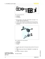
F
ig
.
3
:
L
oosen the plug insert
1
C
able gland
2
P
lug insert
3
P
lug housing
4
R
emove approx
.
5
cm of the cable mantle
,
strip approx
.
1
cm
insulation from the individual wires
5
L
ead the cable through the cable gland into the plug housing
6
C
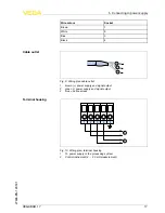
onnect the wire ends to the screw terminals according to the
wiring plan
2
3
1
4
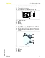
F
ig
.
4
:
C
onnection to the screw terminals
1
C
able gland
2
P
lug housing
3
P
lug insert
4
P
lug seal
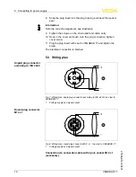
7
S
nap the plug insert into the plug housing and insert the sensor
seal
8
P
lug the plug insert with seal to
VEGABAR
17
and tighten the
screw
T
he electrical connection is
fi
nished
.
P
roceed as follows
:
C
onnection via angle
plug connector with hin
-
ged cover
14
VEGABAR
17
5
C
onnecting to power supply
27636
-
EN
-
120531
Содержание VEGABAR 17
Страница 1: ...Operating Instructions VEGABAR 17 Document ID 27636 Process pressure ...
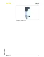
Страница 11: ...Fig 2 Mounting of VEGABAR 17 VEGABAR 17 11 4 Mounting 27636 EN 120531 ...
Страница 34: ...34 VEGABAR 17 9 Supplement 27636 EN 120531 ...
Страница 35: ...VEGABAR 17 35 9 Supplement 27636 EN 120531 ...


