


17
4 Connecting to power supply
MINITRAC 31 • Foundation Fieldbus
62076-EN-190704
4 Connecting to power supply
4.1 Preparing the connection
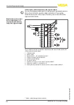
The voltage supply and signal output are connected via the spring-
loaded terminals in the housing.
Connection to the display and adjustment module or to the interface
adapter is carried out via contact pins in the housing.
Proceed as follows:
The procedure applies to instruments without explosion protection.
1. Unscrew the big housing cover
2. Loosen compression nut of the cable gland and remove blind
plug
3. Remove approx. 10 cm (4 in) of the cable mantle, strip approx.
1 cm (0.4 in) of insulation from the ends of the individual wires
4. Insert the cable into the sensor through the cable entry
1
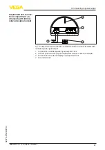
Fig. 9: Connection steps 4 and 5
1 Locking of the terminal blocks
5. Insert a small slotted screwdriver firmly into the rectangular lock
openings of the respective connection terminal
6. Insert the wire ends into the round openings of the terminals ac-
cording to the wiring plan
Information:
Solid cores as well as flexible cores with cable end sleeves are
inserted directly into the terminal openings. In case of flexible cores
without end sleeves, press the rectangular lock opening with a small
screwdriver; the terminal opening is freed. When the screwdriver is
released, the terminal opening closes again.
Connection technology
Connection procedure


