Vega VLB-44 Lantern
25 Jan 2011 - Rev 9
Installation - VLB-44-10 on a Buoy (cont’d)
hardware (no cross ribs, vertical reflectors, etc.). Drill four 9/32” diameter holes through the
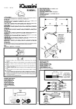
reflector. Install the junction box using the provided hardware. Route the wires through the
stuffing tubes, as shown in Figure 4. Tie the cables to adjacent support structures and cut off the
excess in the box (keep the cable as short as possible). Strip the ends of the wire and insert into
the Euro type terminal strips and secure with a 3/16” flat blade screwdriver. The terminals are
labeled and color coded
black
or
brown
for positive and
white
or
blue
for negative. The
green/yellow wire is a sync wire and is only used to synchronize two lanterns together.
DO NOT
connect it to the buoy hull. The box is gray and may be painted to match the buoy, if desired.
So
la
r Pa
ne
l (+
)
Ba
tt
e
ry
(-
)
S
o
la
r P
a
n
e
l (
-)
Ba
tt
e
ry
(+
)
La
n
te
rn
(
+
)
La
n
te
rn
(
-)
Jumpers
Battery
Stuffing Tube
Solar Panel
Stuffing Tube
Lantern
Stuffing Tube
Note:
Cable sizes for the VLB-44 varies.
Single tier lanterns use a 0.39” dia
cable and multi tier lanterns use a
0.44” dia cable.
For multi tier lanterns, use the
supplied 2E packing.
For single tier lanterns order 2D
packings via MILSTRIP,
NSN5330-00-202-2589
Figure 4.
Cover the window above the label accessing the daylight control to simulate nighttime and check
for proper operation.
Installation – VLB-44-05 on a Structure
Figure 5.
14


