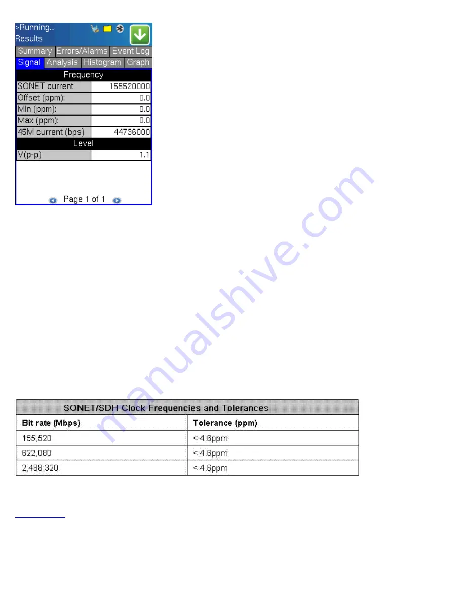
Frequency:
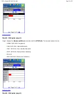
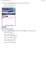
The received signal frequency and offset is measured and displayed.
- SONET Current: Indicates the frequency of the input signal
- Offset: Indicates the difference between the standard rate and the rate of the input signal
- Min (ppm): Indicates the difference between the standard rate and the minimum deviation detected in the input signal
- Max (ppm): Indicates the difference between the standard rate and the maximum deviation detected in the input signal
- 45M Current: Indicates the frequency of the payload data. Options are 1.5M, 2M, 34M are display.
A Min (ppm) and Max (ppm) function can be used to ensure that the received signal is within a certain clock tolerance and that
the network element is transmitting correctly. The frequency limits for the various signal types according to ITU-T
recommendations are presented in the table below.
Low quality clock sources that deviate from the nominal value cause problems in the operation of network elements. It is
necessary and recommended to measure the signal frequency at all hierarchies to reduce synchronization risks. To measure line
frequency in service, the TX150 must be connected to a Protected Monitoring Point (PMP). The frequency of the signal is
normally reported in Hz, while the deviation is reported in ppm. Tolerances for the various clock frequencies of SONET
hierarchies are presented in the table below
Level:
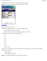
Measures the Peak and Peak-Peak voltage values of the incoming signal. The levels for STS-3 electrical signal
according to GR.253 recommendations are presented.
8.2.5 Results > Histogram (page 1)
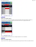
The Histogram tab displays the screen showing a historical record of the Alarms and Errors recorded during the measurement
interval. A dedicated page is available for errors, alarms including BER.
Page 1 displays the
Alarms
associated with the
SONET Alarm
.
TX150 e-Manual D07-00-023 Rev A02
Page 48 of 107


