Module Removal/Installation
Installing A Comm Module
11
Installing A Comm Module
Disconnect, tag and lockout power to the TLS-450PLUS console be-
fore starting this procedure.
1. Referencing Figure 4, open the left and right doors of the console.
2. The Comm Bay is divided into 5 communication slots numbered from 1 to 5 going left to right (see Figure 3).
Only slots 1-3 are available for user-selectable Comm modules (ref. Table 3). The Comm modules in Slots 4
and 5 are fixed and cannot be moved.
3. Using a T-15 Torx driver, loosen the module clamp securing screw and remove the clamp (see Figure 3).
4. Remove the blank cover from underneath the desired comm slot by punching it into the console or by using
pliers to remove it from the inside of the console. Be careful not to damage any internal components in the
process of removing the blank cover.
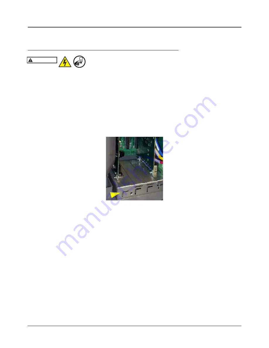
5. Place the new Comm module in the slot. Align the edge connector on the back of the board in the center of the
vertical connector on the Comm Backplane board, then push the board firmly in as far as it can go. The sheet
metal bracket of the Comm module slides into the slot and the front edge of the bracket fits into the keyed slot
in the front of the Comm Bay.
Figure 6. Comm Module Bracket Keyed Slot
6. After the Comm module(s) is installed, replace the comm module clamp and the screw that secures it.
7. Connect applicable interface cable(s) to the module(s) as defined in the POS Application Guide 577013-401.
Record the slot/configurable port for each installed module which will be needed in the communication setup
procedure.
8. Close the console’s front doors, reversing the procedure in Step 2 of “Removing An Interface Module” on
9. Power up the console and perform a DB Restore, then follow the communication setup procedure for the newly
installed module(s) using the TLS-450PLUS Online help.
WARNING
OFF


