background image

9

  Replacing The AC Input Filter And/Or Power Supply Board

1.

Perform all of the Steps in the section entitled “Before Turning Off Power” on page 3.

2.

Open the console left door as described in Step 2 of the section entitled “Replacing Left Door (With Or 
Without Printer)” on page 8.

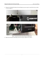
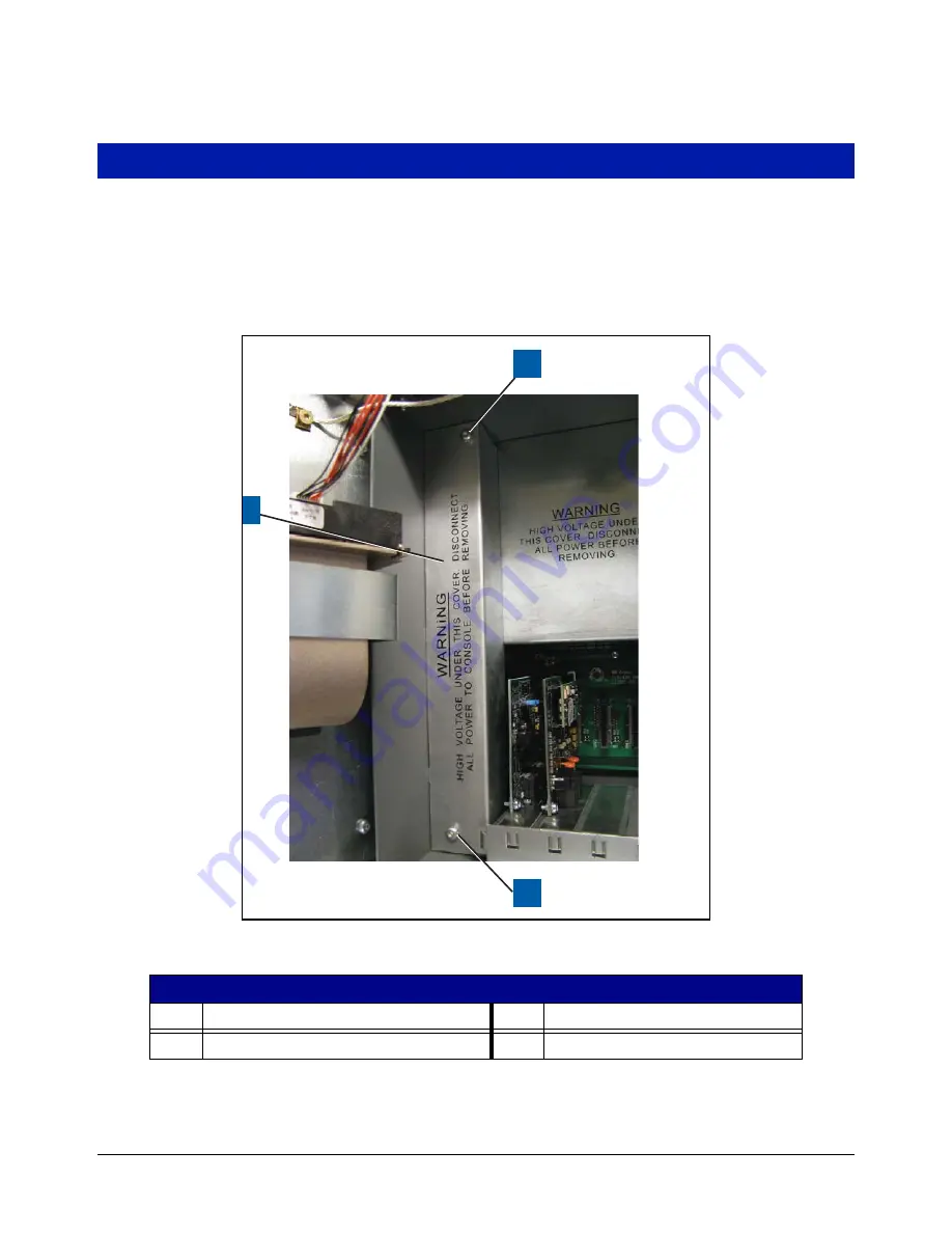
3. Remove the two T15 screws from the AC Channel cover and put the cover and screws aside (see Figure 10).

Figure 10.  Remove AC Channel Cover

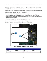
4. Remove the three T15 screws in the AC Input Filter (item 1 in Figure 11).

Legend For Figure 10

Item

Description

Item

Description

1

AC Channel cover.

2

T15 screws (2).

956-8.eps

1

2

2

Содержание TLS-450PLUS

Страница 1: ...Manual No 577014 078 Revision A Hardware Replacement Guide TLS 450PLUS Console...

Страница 2: ...r Terms and Conditions VEEDER ROOT S PREFERRED CARRIER 1 Contact Veeder Root Customer Service at 800 873 3313 with the specific part numbers and quantities that were missing or received damaged 2 Fax...

Страница 3: ...PLUS Console Doors 4 Figure 4 CPU board 5 Figure 5 Remove Display Cables From CPU Board 6 Figure 6 Remove Ground Wire From Ack Switch Display Door 7 Figure 7 Remove Top And Bottom Optional Display Doo...

Страница 4: ...perations training system tests troubleshooting and servicing for all Veeder Root Series Tank Monitoring Systems including Line Leak Detection In addition Contractors with the following sub certificat...

Страница 5: ...RNING Heed the adjacent instructions to avoid damage to equipment property environment or personal injury STATIC SENSITIVE COMPONENTS Wear grounded anti static wrist strap before handling the printed...

Страница 6: ...down arrow in the Backup Destination field to select the Backup thumb drive inserted in Step 1 then follow the on screen instructions to backup TLS 450PLUS console data Figure 2 DB Backup Screen 3 Tu...

Страница 7: ...or 1a pointer up 90 from the connector s fixed base and slide cable end out Legend For Figure 3 Item Description Item Description 1 Left blank door or optional printer door 4 Remove the top and bottom...

Страница 8: ...nnector optional dis play 3 USB Type A connectors 2 12 Features iButton 4 Ethernet RJ 45 connectors 3 13 Backup Battery 5 USB 0 1 pitch header connectors 2 14 Configuration DIP switches 6 Display cabl...

Страница 9: ...Off Power 6 3 Remove the LED Back light cable pointer 2 from CPU board connector see Figure 5 Figure 5 Remove Display Cables From CPU Board 4 Remove the Ground wire at the top of the door see Figure 6...

Страница 10: ...r 7 5 Remove the TLS 450PLUS Ack Switch Panel Display door by removing the top and bottom hinge shoulder screws see Figure 7 Figure 7 Remove Top And Bottom Optional Display Door Hinge Screws 6 Replace...

Страница 11: ...T15 ground clamp screw securing the ground wire at the top of the Printer door and slide it free of the clamp see Figure 8 Figure 8 Removing Printer Door Ground Wire 5 If a printer is installed unplug...

Страница 12: ...2 of the section entitled Replacing Left Door With Or Without Printer on page 8 3 Remove the two T15 screws from the AC Channel cover and put the cover and screws aside see Figure 10 Figure 10 Remove...

Страница 13: ...connectors Lift the AC Input Filter out of the console Remove the two T 15 screws that secure the AC Input board to the AC input board bracket Place fingers under the AC Input board near each of the...

Страница 14: ...s identified by item 3 in Figure 12 9 Disconnect the printer power cable from the Power Supply board connector J1 10 Lift the board out of the console by its edges since there is still undischarged hi...

Страница 15: ...y board With the handle item 3 of Figure 11 of the AC Input Filter against the left side of the console housing line up the two AC Input Filter bottom connectors over the two female connectors items 4...

Страница 16: ...For technical support sales or other assistance please visit www veeder com...

Отзывы: