Installation Guide
Repeater Installation
26
6.
To assure a water-tight seal between the cover and the enclosure, follow these steps:
a. Insert the four cover screws through the cover and then press on the retaining washers to hold the
screws in place.
b. Make sure that the cover gasket is free of dirt and debris on both sides of the gasket and that the inside
of the cover is clean in the gasket area.
c. Position the gasket into the cover groove, assuring that it is pressed fully into the groove and sitting
completely flat.
d. Assemble the cover onto the enclosure, tightening the screws in a couple of turns each. Using an
alternating ‘X’ pattern, continue to tighten the screws until they are all tight.
7.
Hand tighten both cable entry cord grip nuts to prevent water entry!
8.
The other end of the repeater’s dc power cable connects to the receiver’s +15 Vdc output terminal (ref.
item 9 in Figure 24), or to a non-interruptible, Class 2, 15 Vdc power source.
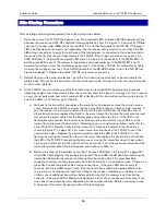
LEGEND FOR NUMBERED BOXES IN FIGURE 25
REPEATER
1.
Red LED – on when power is applied.
2.
Green LED – Unit status
3.
Red LED – Radio status
4.
S1 DIP switch
5.
DC Power input cable
6.
S2 DIP switch
7.
DC power input terminals ( +15 Vdc and ground
)
Pay close attention to the polarity of the +15 V.
Reversing the connections can cause damage to the
TLS RF!
Repeater is only suitable for use in and over a
non-hazardous location.
Figure 25. Wiring the repeater


