Installation Guide
Identifying Devices in the TLS RF Site Network
28
Site Startup Procedure
After installing and wiring all equipment, follow the startup steps below.
1.
Open the cover of the TLS RF, then power it up. The green/red LEDs indicating RS-485 network activity
between the receiver and TLS RF should be flashing rapidly (ref. item 2 in Figure 11 on page 14). If Yes,
continue to the next step. If No, check the red LED. If it is not flashing, replace the TLS RF. If the green
LED is not flashing, the receiver is not responding. Go the receiver and remove its cover. Check the RS-
485 wiring connections to verify that each wire of the twisted pairs is connected to the same terminal in
the receiver that its other end is connected to in the TLS RF. If the wiring connections are correct, the
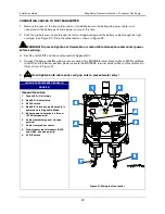
PWR LED (item 1 in Figure 24) and green LED (item 2 in Figure 24) should be lit. If the PWR LED is lit,
but the green LED is not lit, the receiver is inoperative and needs replacing. If the PWR LED is not lit,
measure the voltage across the twisted pair power wires, it should be +15 Vdc. To isolate a faulty cable,
measure the voltage across the +15 and GND terminals of the RS-485 terminal strip in the TLS RF (ref.
Figure 6 on page11). Replace the cable, TLS RF, or receiver as necessary.
2.
Referencing your site network worksheet, go to the first transmitter and connect its power cable to the
battery pack. This will put the transmitter into the continuous mode, ‘forcing’ it to transmit every 6 seconds
for 30 minutes (default).
3.
At the TLS RF, you should see one of the 8 red transmission received LEDs flashing every 6 seconds,
indicating receipt of each transmission from the transmitter (item 5 in Figure 11 on page 14). If yes, record
on your site network worksheet which number LED is flashing for this transmitter and then go to step 3a. If
one of the LEDs is not flashing, go to step 3b.
a.
Go back to the transmitter and replace the sump lid, or if a dispenser, close the sump’s access
cover. Return to the TLS RF and verify that the same LED continues to flash every 6 seconds. If
yes, the receiver is continuing to communicate with the transmitter after the manhole cover or
other obstruction was replaced. Go back to the same transmitter, remove the manhole cover and
disconnect the power cable from the battery pack and continue to step 4. If the LED is not
flashing every 6 seconds, the receiver is not picking up the transmitter’s signal. Return to the
transmitter and remove the obstruction. Referring to your site network worksheet, verify that the
correct Site ID is entered. Verify that the transmitter’s antenna is oriented to the receiver as
shown in Figure 17 on page 18, if it is move it around and recheck at the TLS RF to see if the
new position helps. Replace the obstruction and recheck the LED in the TLS RF. If it is not
flashing, try moving the transmitter down in the sump, then replace the obstruction and recheck
the LED in the TLS RF. If reorienting the antenna or moving the transmitter doesn’t help, make a
note on your worksheet that the signal from this transmitter is not being received, disconnect the
transmitter power cable at the battery pack, and continue to Step 4.
b.
Remove the cover of the problem transmitter. The green LED (item 1 in Figure 21 on page 22)
should flash indicating that the probe is being read. The red LED should also flash indicating the
transmitter linked with the receiver and transmitted the probe’s data. This green/red flash
sequence should occur every 6 seconds while the transmitter is in continuous mode. If there is no
green flash, check the probe cable’s wiring connections. If the green LED flashes every 6
seconds, but the red LED doesn’t flash, then the transmitter is reading the probe data, but for
some reason is not linking with, and transmitting to the receiver. However, you will have to wait
until you check additional transmitters before determining that the receiver is not functioning
correctly. If the green LED is blinking quickly (about a tenth of a second) every 6 seconds, it can
mean one of several probe errors depending on the number of blinks. Before continuing to step
4, disconnect the transmitter power cable at the battery pack.


