9-4
Calibration and Maintenance
c.
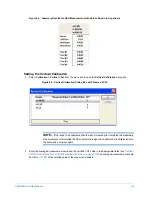
Click any underlined scan parameter to open the
Scan Parameters
dialog box.
d.
Select
Use Current Location
.
e.
In the Profile Section, select
Hills&Valleys
.
10
Perform the preliminary scans:
a.
Select
Run > Scan Here
. The scan should be at least 2500
μ
m
in length
.
b.
As you observe the profile trace in the
Data Plot
window, do the following, as necessary:
•
If the profile trace goes out of range, re-level the stage.
•
If the first falling edge is not at 375
μ
m
on a vertical standard or the first rising edge is not at 375
μ
m
on a step-height standard , adjust the scan start position until it is within 50
μ
m.
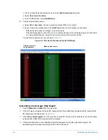
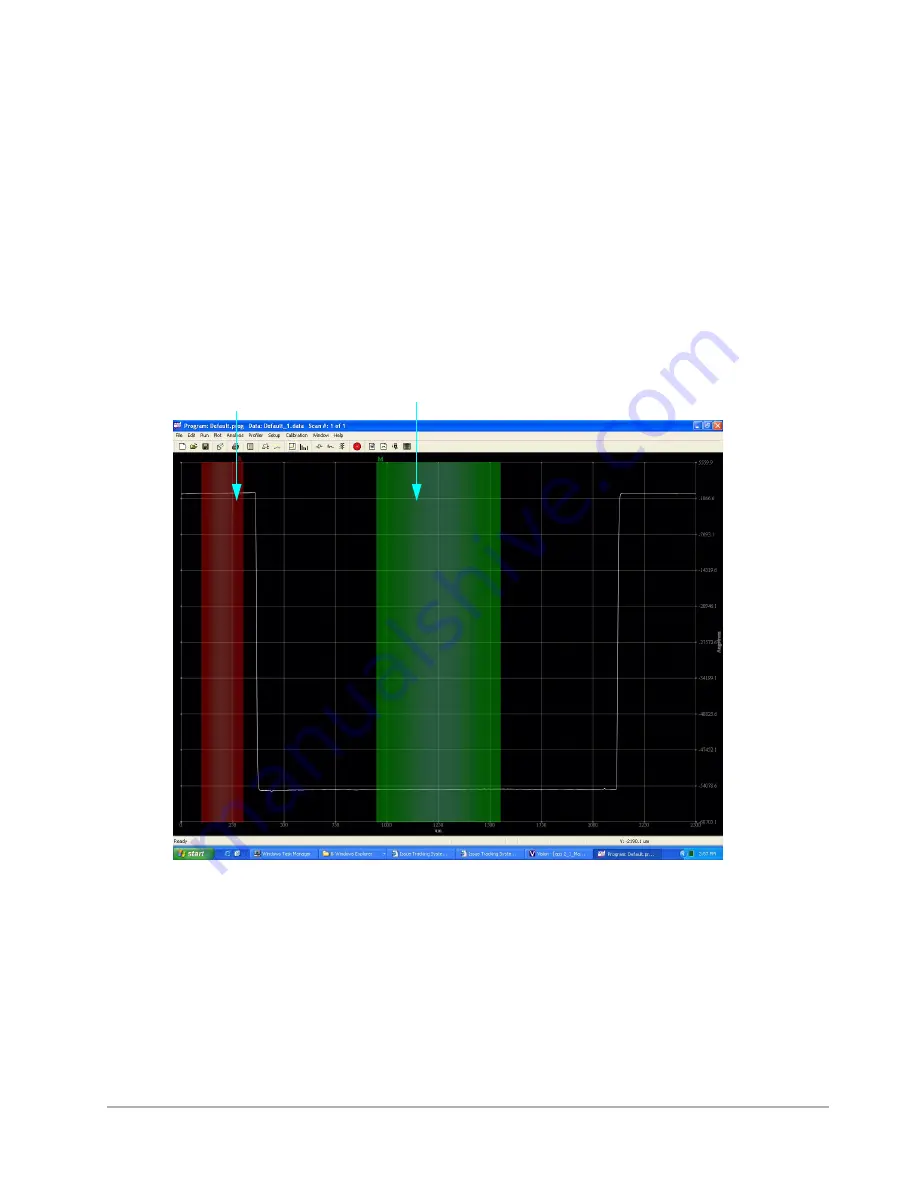
The plot should resemble the one shown in
.
Figure 9-3: Plot from Calibration in the 65
kÅ Range
Calculating the Average Step Height
1
Select
Calibration > Vertical
from the menu bar.
2
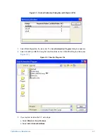
If the VCF was not cleared for the 65
kÅ range prior to the preliminary measurements
, select the 65
kÅ range
and click
Clea
r (see
).
3
Select
Run > Auto Program
from the menu bar (or press the F5 key on the keyboard) to run the five scans
using the 65K_SIMETRICS.prog automation program.
4
Follow the instructions in the Calibration Wizard that appears. During the automation program, the
database logs the Average Step Height (ASH) from all five scans.
Reference cursor
and bandwidth
Measurement cursor
Содержание Dektak 150
Страница 1: ......
Страница 2: ...P N 980 294 Standard P N 980 298 Cleanroom Revision A DEKTAK 150 SURFACE PROFILER USER S MANUAL ...
Страница 7: ......
Страница 17: ......
Страница 81: ......
Страница 105: ......
Страница 149: ......
Страница 191: ......
Страница 251: ......
Страница 257: ...A 6 Facilities Specifications Figure A 6 Dektak 150 without Enclosure Side View ...
Страница 258: ...Facilities Specifications A 7 Figure A 7 Dektak 150 Dimensions without Enclosure Top View ...
Страница 259: ...A 8 Facilities Specifications Figure A 8 Dektak 150 without Enclosure Center of Mass ...
Страница 273: ......
Страница 283: ......
Страница 320: ...3D Mapping Function E 37 Figure E 26 Database Options Button Figure E 27 Database Options Dialog Box ...
Страница 321: ......
Страница 331: ......
Страница 333: ......
Страница 336: ......
Страница 337: ......
Страница 349: ......

