■
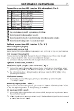
Audio input to chamber D2 (adapter cable accessories), Fig. 7:
☞
Connect the right-hand channel of the AV source’s audio output to the adapter
cable’s red socket.
☞
Connect the left-hand channel of the AV source’s audio output to the adapter
cable’s white socket.
Hand brake signal
☞
Connect the hand brake signal via the unit’s grey cable.
✎
When the hand brake is applied, the signal must lie at ground potential.
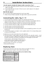
Connecting the radio, Fig. 9 - 11
1. Connect the antenna extension cable to the vehicle antenna’s plug.
2. Insert antenna plug E into the antenna socket. If necessary, use a suitable antenna
adapter. Use the hook (J) on the back of the unit for secure attachment.
3. Connect the ISO-A extension cable to the vehicle ISO power supply plug.
4. Connect the ISO-B extension cable to the vehicle ISO loudspeaker plug.
5. Insert ISO plug A into the radio ISO socket A’.
6. Insert ISO plug B into the radio ISO socket B’.
7. Connect the monitor via the supplied cable to the corresponding socket on the unit’s
front panel.
8. Connect the navigation computer via the supplied cable to the corresponding socket
on the unit’s front panel.
If extensions are to be connected to the unit (optional):
9. Push all chamber C plugs together and insert them into the radio ISO socket C’. Insert
the green connector C2 between the yellow connector C1 and the blue connector C3.
At least one of these connectors is required for C2 to engage into the socket:
Yellow plug C1: Left chamber of ISO socket C1’.
Green plug C2: Centre chamber of ISO socket C2’.
Blue plug C3: Right chamber of ISO socket C3’
10.Insert plug D into socket D’ on the radio.
11.Reconnect the battery.
Replacing fuses
The ISO terminal block at the rear of the radio is equipped with a fuse.
Additional fuses are looped in via the ISO extension cable.
A
A fuse should be replaced only with one of an identical rating.
Fuse
Value
Unit:
10 A
ISO extension cable:
12-V permanent positive:
10 A
12-V ignition / ACC:
250 mA
Installation instructions
22

