


7
EN
1968 FORD
®
F-100 ASCENDER
®
, BND • INSTRUCTION MANUAL
PRECAUTIONS
»
Never touch moving parts.
»
Never disassemble while the batteries are installed.
»
Always let parts cool before touching.
GEARING
Your vehicle has been equipped with the optimal gearing for the stock
platform. It off ers an ideal balance between speed, power and effi
ciency.
Should you decide to customize your vehicle with optional batteries or
motors, it may be necessary for you to change the pinion or spur gear.
Installing a pinion gear with fewer teeth or a spur gear with more teeth
will provide greater torque but will reduce top speed. Likewise, a pinion
gear with more teeth or a spur gear with fewer teeth will reduce torque
and increase top speed. Care should be taken when installing larger
pinion gears as this can “overgear” the vehicle, resulting in overheating
of the motor and ESC. When testing diff erent gearing options, pay close
attention to the temperature of the motor and speed control to ensure
you are operating within the temperature range of the components.
The motor or ESC should never be so hot that it cannot be touched. If
temperatures are too hot, a diff erent gearing combination with a lower
pinion gear and/or higher spur gear is suggested.
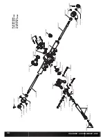
CHANGING THE PINION GEAR/GEAR RATIO
The following instructions are for replacing a worn pinion gear. If you are
changing the pinion gear size please refer to “Setting the Gear Mesh.”
1. Remove the spur gear cover.
2. Loosen the pinion gear set screw to remove the installed pinion gear.
3. Loosen the motor screws and slide the motor back.
4. Place the new pinion on the end of the motor shaft so the set screw is
located over the fl at area on the shaft.
Position the teeth on the pinion gear so they line up with the spur gear
and secure the pinion gear onto the motor shaft by tightening the set
screw.
DYNAMITE® 540 BRUSHED MOTOR 35T (DYNS1216)
/ / / / / / / / / / / / / / / / / / / / / / / / / / / / / / / / / / / / / /
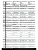
TROUBLESHOOTING GUIDE
/ / / / / / / / / / / / / / / / / / / / / / / / / / / / / / / / / / / / / / / / / / / / / / / / / / / / / / / / / / / /
PROBLEM
POSSIBLE CAUSE
SOLUTION
Vehicle does not operate
Battery not charged or plugged in
Charge battery/plug in
ESC switch not “ON”
Turn on ESC switch
Transmitter not “ON” or low battery
Turn on/replace batteries
Motor runs but wheels do not rotate
Pinion not meshing with spur gear
Adjust pinion/spur mesh
Pinion spinning on motor shaft
Tighten pinion gear setscrew on motor shaft fl at spot
Transmission gears stripped
Replace transmission gears
Drive pin broken
Check and replace drive pin
Steering does not work
Servo plug not in receiver properly
Make sure the steering servo plug is connected to the
receiver steering channel, noting proper polarity
Servo gears or motor damaged
Replace or repair servo
Will not turn one direction
Servo gears damaged
Replace or repair servo
Motor does not run
Motor wire solder joint is damaged
Resolder the motor wire with the proper equipment
Motor wire broken
Repair or replace as needed
ESC damaged
Contact Horizon Hobby Product Support
ESC gets hot
Motor over-geared
Use smaller pinion or larger spur gear
Driveline bound up
Check wheels and transmission for binding
Poor run time and/or sluggish acceleration
Battery pack not fully charged
Recharge battery
Charger not allowing full charge
Try another charger
Driveline bound up
Check wheels, transmission for binding
Poor range and/or glitching
Transmitter batteries low
Check and replace
Vehicle battery low
Recharge battery
Loose plugs or wires
Check all wire connections and plugs
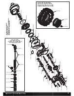
SETTING THE GEAR MESH
The gear mesh has already been set at the factory. Setting it is only
necessary when changing motors or gears.
Proper gear mesh (how gear teeth meet) is important to the performance
of the vehicle. When the gear mesh is too loose, the spur gear could be
damaged by the pinion gear on the motor. If the mesh is too tight, speed
could be limited and the motor and ESC will overheat.
1. Remove the spur gear cover.
2. Loosen the motor screws and slide the motor back.
3. Put a small piece of paper between the pinion and spur gears.
4. Push the gears together with moderate pressure and hold in place
while tightening the motor screws.
5. Remove the paper. Check the mesh at 3–5 diff erent locations around
the spur gear for minimal movement.


