


MOUNTING SWITCHES 13
CONNECTION FOR 0-10 V SIGNAL
(BUILDING MANAGEMENT SYSTEM
APPLICATION)
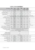
With 0-10 V, the flow rate can be steplessly adjusted between the minimum
and maximum flow rate of the ventilation unit. This corresponds to the following
values:
1 V
T350
T500
40 m³/h
60 m³/h
1
– 10 V
Linear relationship
Linear relationship
10 V
350 m³/h
500 m³/h
To connect a 0-10 V signal, the cover on the ventilation unit must be
opened in a correct manner so that the circuit board can be reached. This
method can be found in the chapter on the electric pre-heating element.
Next, a correct cable must be led to the PCB through the grommet in the
ventilation unit.
Finally, connect the control signal to terminal X26 "Building
control system connection" according to the following
diagram.
Circuit board T350 /T500
X
X
9
X6X22
X23
8
X5X21
X20
X15X26
0-10V signalGround
Grommet provided in
ventilation unit.
2 x 1.5 mm2
(maximum)
Building management
system


