background image


Touch Screen Definition Cont.


Connecting the touch screen 

1.  Make sure all optional cables have been received. 
2.  Connect one end of the 6 foot touch screen serial cable to the touch screen port D9        

connector on the side of the monitor. 

3.  Connect the other end to any communications port on the host computer. 
4.  Tighten the captive screws on the cable connector to secure it.  

Touch Screen Serial Interface


All touch controllers are configured by default to provide serial communications at 9600 baud, 8 data 
bits, 1 stop bit, no parity. For Vartech flat panels equipped with touch screens, a serial  
communications cable is required. This 6 foot cable comes with the unit in the accessory kit. 
The cable is a straight wired serial (RS-232) cable with a male DE-9 D-shell connector on the 
monitor end. The cable provides a communications channel between the touch screen 
controller, which is mounted inside the monitor, and an RS-232 serial port on the host computer. 
Because the touch controller obtains power from the monitor's power supply, no external touch power 
connections are necessary. 
Software supplied with the touch screen must be loaded on the host computer to handle 
communications with the touch controller over the channel. 
Because the touch screen emulates a mouse, there may be compatibility issues involving how the touch 
screen emulates mouse buttons, especially multiple buttons. 


Setting up the Touch Screen Interface 

Enabling the Touch Screen Interface 

The Flat Panel Monitor provides a female DE-9 connector for the touch interface. This connector       
provides the serial interface for the touch controller. 
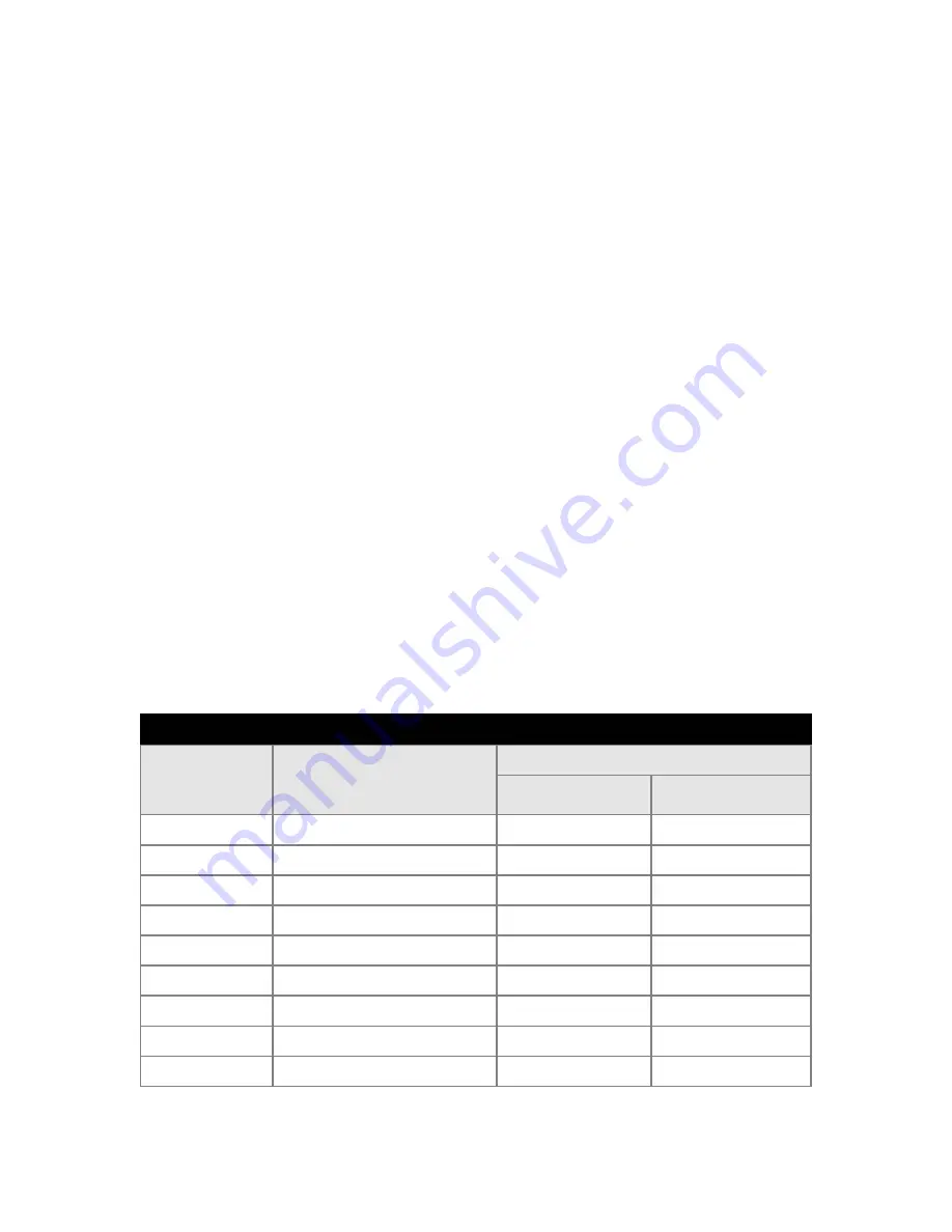
Interconnecting wiring to the host serial port connection is shown in the following table. 

18 

4.2 

4.3 

4.4 

Touch screen Interface  

Monitor 

(DCE Device) 

DE-9 (Female) 


Host (DTE Device) 


DE-9 (Male) 


DB-25 (Male)


Not Connected (DCD) 

Transmit Data (TXD)  

Receive Data (RXD)  

Data Terminal Ready (DTR)  

20 

Common Signal Return (SG)  

Not Connected (DSR)  

Request To Send (RTS)  

Clear To Send (CTS)  

Not Connected  

22 

Signal Description 


Содержание VT201CM

Страница 1: ... 20 1 Flat Panel LCD Displays VT201CM VT201PM VT201RM VT201MM VT201WM VT201YM User s Guide Read these instructions completely before attempting to operate your new Color Display VarTechSystemsInc Solutions for Demanding Applications Industrial CRT and Flat Panel Displays ...

Страница 2: ... 2000 Touch Drivers 20 Section 2 Section 5 Display Setup Troubleshooting Tips 21 Display Features 4 Unpacking The Display 4 Section 6 Included Parts 4 Cleaning Maintenance 22 Connecting Your Display 5 Signal Connections 5 7 Section 7 Mechanical Drawings Section 3 Console Panel Mount Procedure 23 Getting Started VESA Wall Mount Procedure 24 Operator Controls and Indicators 8 Rack Mount Procedure 24...

Страница 3: ...acking materi als should be saved for possible inspection by the shipping company and the shipping company and VarTech should be notified immediately NOTE Please save the packaging for re use in case the monitor should ever have to be shipped to a new location CHECKING PACKAGE CONTENTS All monitors are supplied with a User s Manual and with cables and other optional accessories as specified by the...

Страница 4: ...sure what type of power supply you have consult with your service or maintenance department Overloaded AC outlets and extension cords are dangerous So are frayed power cords and broken plugs They may result in a shock or fire hazard Call your service technician for replacement Do not Open the Display There are no user serviceable components inside There are Dangerous High Voltages inside even when...

Страница 5: ...Matrix LCD permanently Do not press the LCD screen with your finger for a long time as this may cause some afterimages Some dot defects may appear as Red Green or Blue spots on the screen However this will have no impact or effect on the display performance If possible use the recommended resolution to obtain the best image quality for your LCD display If used under any mode except the recommended...

Страница 6: ... optional Touch System The VT201 Military Marine Series has an integrated 115 220VAC supply as standard on all models Unpacking and setting up your display Before unpacking the shipping carton should be inspected for damage Then the carton should be carefully opened and the monitor removed The monitor itself should be carefully inspected for shipping damage If damage has occurred the shipping cart...

Страница 7: ...265 VAC 47 440Hz FUSE POWER VIDEO IN SERIAL 85 265 VAC 47 440HZ FUSE Figure 1 Rear view showing connectors You can use an HD 15 connector cable or a BNC adapter cable to connect the flat panel monitor to the host computer The HD 15 video cable supplied in the kit you use with this monitor is equipped with a conventional HD 15 connector at each end HD 15 Video Connector The following table provides...

Страница 8: ...n green only three of the cable s five BNC connectors are used When the source provides RGB video and separate composite sync four of the cable s five BNC connectors are used When the source provides RGB video and separate horizontal and vertical sync all five of the cable s BNC connectors are used Source w 3 BNC Source w 4 BNC Source w 5 BNC Signal Monitor HD 15 BNC R BNC R BNC R Analog Red 1 BNC...

Страница 9: ...pproved 10 stranded wire The wire should use properly color coded insulation Power and Ground Connections 7 WARNING To ensure against fire or shock hazards the monitor chassis should be con nected to an earth ground by a path that is independent of the power cord While the AC power cord provides a ground wire the power cord ground can be defeated by use of an extension cord or 3 prong to 2 prong A...

Страница 10: ...ing section The luminance control controls the backlight The range of the control is determined by the brightness setting made with the OSD 8 The monitor is pre aligned at the factory However minor adjustments are usually necessary following installation to optimize the monitor s performance with a particular video source and particular video formats This section of the manual describes the operat...

Страница 11: ...ons Likewise the VT201 Series monitors provide the best possible imagery when the video source is set up to support a color depth of 24 bits pixel because this color depth corresponds to the capabilities of all these monitors allowing them to display over 16 million distinct colors at once In order to support a resolution of 1280x1024 or 1600x1200 and a color depth of 24 bits pixel a video source ...

Страница 12: ...hese colors constitute a subset of a potentially much larger color set typically a set of 262 144 distinct colors Any 256 member subset of this larger set of colors may be displayed by changing the palette register values On the other hand when video RAM is organized to provide 16 or 24bpp each pixel value in memory becomes a direct representation of a color In this case the palette registers are ...

Страница 13: ...dth of the screen Use the Source button to exit and return to the Picture submenu 3 Adjust clock phase Put an image containing closely spaced vertical lines on the screen Press the Menu button to invoke the Main Menu Use the Left Right buttons to move to the Picture submenu and press the Menu button to select it Once in the Picture submenu use the Up Down buttons to move to the Phase item Use the ...

Страница 14: ...utton to exit the menu or to move up a level MENU Press to enter the Main Menu or move down to a submenu in the Main Menu UP Navigate the menu items DOWN Navigate the menu items LEFT Navigate the menu items and make settings RIGHT Navigate the menus items and make settings AUTO Press to perform an automatic adjustment procedure Only applicable for analog RGB source modes Figure 3 OSD Controls Main...

Страница 15: ...ce The phase should be set after setting the horizontal size and the frequency while observing an image presented by the external source Set the phase to obtain the sharpest and most distinct vertical lines H Position Set the horizontal position to center the image on the screen Make this adjustment after making a first adjustment of horizontal size It might be necessary to alternate between horiz...

Страница 16: ...e screen in the absence of user input If there is no user input for the duration of the timeout period the OSD will disappear Language LANGUAGE refers to the national language in which the OSD menu items will be presented At present only English is supported Use the UP or DOWN button to select the desired function Use the LEFT or RIGHT button to set the value of the selected function Use the SOURC...

Страница 17: ...e the SOURCE button once a setting has been made and again to return to the Main Menu Freeze Frame Info Select this item to obtain a display of information about the current video source including horizontal frequency vertical frequency refresh rate etc There are no settings to make 15 Utility Submenu NOTE When no video signal is applied to any of the monitor s video inputs the OSD will present th...

Страница 18: ... the SOURCE button once a setting has been made and again to return to the Main Menu Brightness Scaling Mode When the format of the video presented by the external source does not correspond to the monitor s native format the image is displayed in one of three ways 1 it is scaled to fit the screen 2 it is scaled up but the aspect ratio is preserved 3 it is not scaled but mapped to the screen pixel...

Страница 19: ...there is a very low voltage applied to the X and Y axis of the touch screen This current is applied to ITO Iridium Tin Oxide that is sputtered onto a polyester membrane When you touch the screen you are changing the resistance on both the X and Y axis producing an analog value that references a particular location This type of screen can be activated with a gloved finger or mechanical stylus The t...

Страница 20: ... port on the host computer Because the touch controller obtains power from the monitor s power supply no external touch power connections are necessary Software supplied with the touch screen must be loaded on the host computer to handle communications with the touch controller over the channel Because the touch screen emulates a mouse there may be compatibility issues involving how the touch scre...

Страница 21: ... your computer 2 Insert the MonitorMouse for Windows 95 disk into drive A 3 Click the Start button then click Run 4 Type a setup in the space provided and press Enter 5 Follow the directions on the screen 6 MonitorMouse for Windows 95 provides two installation options Most users should select Typical the default and click Next to continue Custom allows you to install the sample touch screen progra...

Страница 22: ...want to use in the Touch screen Control Panel Click OK to confirm that the Setup is correct 8 Complete the Setup program 9 Shutdown and restart Windows 2000 Continue the steps on the next page 10 Click the Start button then click Settings then click Control Panel 11 Double click Elo Touch screen to run the Touch screen Control Panel 12 Click the Calibrate button and touch each of the three targets...

Страница 23: ... screen saver software at the video source Activate the monitor s OSD using either the AUTO button or the SOURCE button to verify that the monitor is capable of displaying a locally generated image Check for presence of video signals from the external source Connect source to a different display device A display is present but it appears distorted for example circles appear as ellispes Use the OSD...

Страница 24: ...or polycarbonate shield that is installed over the screen Abrasive and certain chemical cleaners can easily damage the surface Never use alcoholic or ammoniac cleaners to clean the polycarbonate shield or a touch screen Replacing a Line Cord To avoid shock and fire hazards the monitor s power cord should be replaced if the insulation becomes broken or if it develops a loose internal connection Oth...

Страница 25: ...accommodate that part of the monitor s enclosure that projects backward behind its front panel The monitor must drop into this cut out in such a way that the back surface of its front panel rests against the front surface of the console panel on all four sides Drill holes around the periphery of the cut out just made in the console panel The holes should be located in such a way that they will ali...

Страница 26: ...nstallation power ground and video connections should be made prior to installing the monitor on the rails Please refer to the following sections of the manual for connection guidelines Position the monitor on the rails and run screws through the front panel holes into the pre installed clip nuts NOTE About Universal vs Wide hole spacings on EIA rack cabinet rails The mounting rails that run verti...

Страница 27: ...20 1 PowerVue User Guide 150 055 25 ...

Страница 28: ...26 ...

Страница 29: ...e Time TR 5ms TD 20ms Back Lights Cold Cathode 50 000 Hrs Half Life Video Connectors DVI I integrated digital analog DIN S video RCA composite video Video Input RGB Analog 0 7V p p 75ohm digital TMDS Sync Separate TTL H V Composite TTL H V SOG Colors Supported 16 777 216 Power Input AC 100 240V 50 60Hz 1 0A Power consumption Normal 100 Watts Operating Temperature 20 to 55ºC Operating Temperature 2...

Страница 30: ...2 15 03 VARTECH SYSTEMS HEADQUARTERS 11529 Sun Belt Ct Baton Rouge Louisiana 70809 Toll Free 800 223 8050 International Phone 001 225 298 0300 Fax 225 297 2440 E mail sales vartechsystems com www vartechsystems com ...

Отзывы: