V-AVM650D
7
Installation
•
Be sure to connect the color-coded leads according to the diagram. Incorrect connections may cause the unit
to malfunction or damage the vehicle’s electrical system.
•
Be sure to connect the speaker (-) leads to the speaker (-) terminal. Never connect the left and right channel
speaker cables to each other or to the vehicle body.
•
Make sure all the connections are completely correct before turning on your unit.
•
When replacing the fuse(s), the replacement must be of the same amperage as shown on the fuse holder.
•
Do not block vents or radiator panels. Blocking them will cause heat to build up inside and may result in fire.
•
After completing the installation, please press RESET button on the unit with pointed object (such as ball-
point pen) to set the unit to initial status.
•
Use only the parts included with unit to ensure proper installation. The use of unauthorized parts can cause
malfunction.
•
Consult with your nearest dealer if installation requires the drilling or other modifications of the vehicle.
•
Install the unit where it does not interfere with driver’s actions and cannot injure the passenger if there is a
sudden stop, like an emergency stop.
•
The semiconductor laser will be damaged if it overheats, so don't install the unit in hot place, for example,
near a heater outlet.
Содержание V-AVM650D
Страница 3: ...V AVM650D 3 Troubleshooting Guide 57 Specifications 58 ...
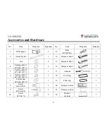
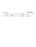
Страница 6: ...V AVM650D 6 11 Screw M5 0x9 0 6 23 Warranty Card 1 12 Extended box 1 24 Consumer Information 1 ...
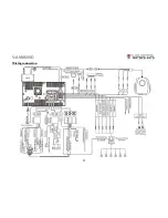
Страница 11: ...V AVM650D 11 Wiring connection ...
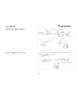
Страница 12: ...V AVM650D 12 Parking brake cable connections Reverse driving cable connections ...
Страница 69: ...V AVM650D 69 Подсоединение к стояночному тормозу Подсоединение кабеля заднего хода ...
Страница 70: ...V AVM650D 70 Схема электрических соединений ...


