background image

23

Värmebaronen EP 26E and EP 42E

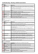
Troubleshooting

Intervention that requires tools must be performed by a qualified electrician! 
Start troubleshooting by looking at the status indicator, see "menu Management".

Fault

Possible cause of fault

Action

Indicators and 
display off. 

Electric boiler has no power. Check the main fuses.
Main and/or control switch off. Set switch to position. Activation delay locks the boiler if it has had 

no power.

Control fuse triggered.

Check where the short circuit is, take remedial action and then reset 
the fuse.

Malfunction of the control 
electronics

Change the circuit board

Group fuse is triggered.

Immersion heater faulty.

Check the insulation of the immersion heaters, which are accessible 
when the boiler's lower front plate and insulation are removed. 
Replace defective immersion heater. When the new immersion heater 
is in place, check that the power cables are not against the electrical 
connections.

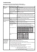
The boiler does not step 
up power even though 
the temperature in the 
boiler is lower than the 
set value.

The boiler stages have been 
limited.

Check the "Number of output stages" setting.

The boiler is controlled by 
external signal.

Check the voltage of the signal.

Outside temperature 
compensator connected.

Check the settings for the UTK function.

The temperature sensor 
is defective.

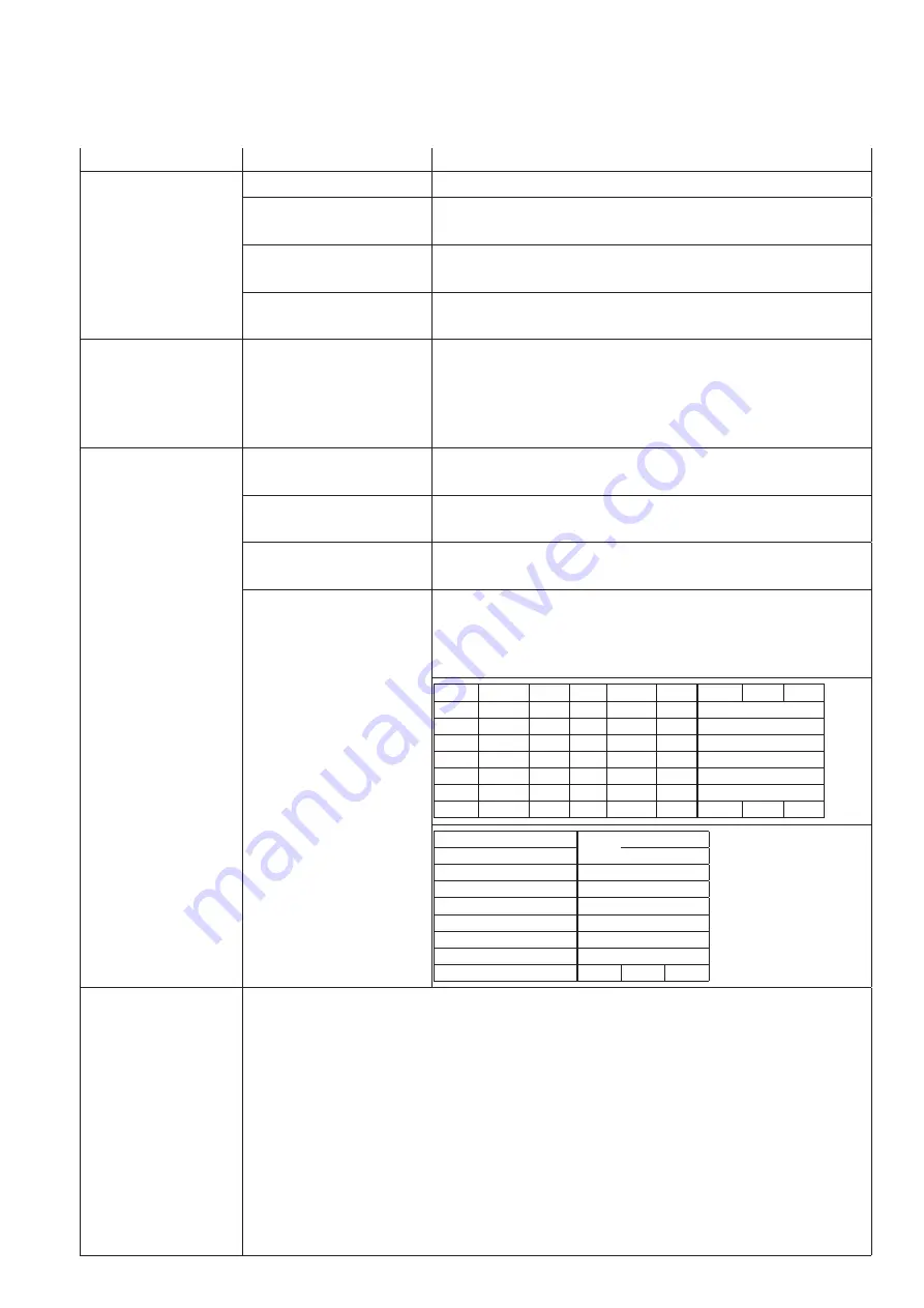
Take control measurements of the temperature sensor. 
The sensor must not be connected to the circuit board during 
resistance measurement. When the boiler is energized, voltage is 
measured in the sensor’s connection points at the PCB.

Boiler temperature sensor

°C

k

Ω

V

°C

k

Ω

V

°C

k

Ω

V

5

141.9

4.7

40

30

3.7

75

8.2

2.3

10

111.6

4.6

45

24.6

3.6

80

6.9

2

15

88.3

4.5

50

20.2

3.3

85

5.8

1.8

20

70.3

4.4

55

16.7

3.1

90

5

1.7

25

56.3

4.2

60

13.9

2.9

95

4.2

1.5

30

45.4

4.1

65

11.6

2.7

100

3.7

1.3

35

36.8

3.9

70

9.7

2.5

Outdoor temperature sensor,
Option

°C

k

Ω

V

°C

k

Ω

V

-40

88.7

4.5

0

8.8

2.3

-35

64.2

4.3

5

6.8

2.0

-30

47.0

4.1

10

5.4

1.7

-25

34.7

3.9

15

4.2

1.5

-20

25.9

3.6

20

3.4

1.3

-15

19.5

3.3

25

2.7

1.1

-10

14.8

3.0

30

2.2

0.9

-5

11.4

2.7

Uneven regulation; 
the boiler increases 
a few stages and 
is then reduced 
immediately etc.

Water flow through the electric boiler too low. 
Check that circulation pumps and valves are working.
This is an easy way to get an idea of the level of flow through the boiler: 
1. Limit the power stages of the boiler so that the power is constant, for example to four power stages.
2. Let the boiler's temperature become stable.
3. Measure the temperature increase between the return and flow lines of the boiler.
4. Calculate the flow through the boiler using the formula below.
5. Check against the flow details whether the flow is adequate.
 

q = P / (

t x 1.16)   Q = water flow in m3/h. (m3/h x 1000/3600 = litre/second)  

P = electrical boiler delivered output in kW  

 t = temperature difference between the boiler's return and flow lines in °C. 

1.16 = water's thermal absorption coefficient.

Содержание EP 26 E

Страница 1: ...E P 2 6 _ 4 2 E _ 2 0 0 8 2 7_ e n r e v 8 k r a f t 1 1 6 d i s p l a y v 1 0 6 p a n n t y p 7 Installation and maintenance EP 26 E EP 42 E Seven stage electric boilers 26 42 kW...

Страница 2: ...UTK function row 16 Max boiler temperature row 17 Max boiler temperature setting row 18 manual activation of rows 19 20 and 21 row 19 Manual activation test run output stage row 20 Manual circulation...

Страница 3: ...ed Boiler type EP 26 E EP 42 E Manufacturing number Installation date Installation engineer Tel Other Notes Number of output stages Factory setting 7 Circulation pump Factory setting 0 Main fuse Facto...

Страница 4: ...he reset plug is removed during reset Never carry out maintenance work service on pressure bearing parts when they are pressurised The boiler may not be used by children or people with physical or men...

Страница 5: ...he input can be adapted for 0 10 or 0 20 mA Output available 0 10 Vdc for external display of connected output Outdoor temperature compensator An outdoor temperature sensor is available as an accessor...

Страница 6: ...eously pressing and on any menu row in User Level The same action is used to return to User Level Access to the Advanced Service level is obtained by setting the value 21 in the last menu bar in Servi...

Страница 7: ...w is displayed All active alarms are acknowledged at the same time The red indicator will stop flashing and return to solid red The display remains on the alarm row and displays the alarm code s Once...

Страница 8: ...evel adjustment 1 Displays the value if UTK is enabled in the Factory menu and in the Service menu otherwise 5 30 20 Display at un activated UTK function optional or UTK function closed UTK curve slop...

Страница 9: ...t day and a 70 C supply temperature for a high temperate system The coldest day is the lowest temperature that normally occurs in the location Adjustment of basic setting For low temperatures select a...

Страница 10: ...12 17 3 3 11 25 16 2 18 25 9 4 15 0 21 6 24 34 6 5 18 75 27 0 30 43 2 6 22 5 32 4 36 51 9 7 26 25 37 8 42 60 5 1 7 7 Display at un activated UTK function optional or UTK function closed UTK min Limit...

Страница 11: ...he same parameter is used regardless of the selection above Must be adjusted if method Absolute temperature 6 95 C 10 Manual activation of rows 18 19 and 20 0 Off 1 limited to 15 minutes 0 Manual acti...

Страница 12: ...the installation service level to 1 Fast stepping is deactivated automatically after 15 minutes Activation delay According to the recommendations a maximum of 50 of the output should be connected imme...

Страница 13: ...can be changed in the Advanced Service menu on rows 16 and 17 Action in the event of a risk of freezing The boiler must not be in operation if you suspect that any part of the heating system is froze...

Страница 14: ...oxygen free What is important is that the system is leak proof so that the water is not replaced with new oxygen rich water and the water is not oxygenated during operation In large systems it is impo...

Страница 15: ...ner that protects against freezing To avoid oxygenation of the water the distance between the highest point of the heating system and the expansion tank must not be less than 2 5 m Pressure height mus...

Страница 16: ...ical installation Electrical installation shall be carried out in accordance with the applicable regulations by an authorized electrical installer or by someone who is covered by the company s self in...

Страница 17: ...tivation is done in advanced service level row 13 GND SIGNAL 1 5 2 1 2 3 4 8 Output control 0 10 mA 0 20 mA By connecting a resistor with a value as shown in the following figure the number of output...

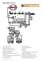
Страница 18: ...on 230V 4 External alarm indicator connection 230V 5 Connection current transformers 6 Optional room unit connection 7 Outside temperature sensor alternative temperature connection 8 Blocking voltage...

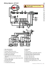
Страница 19: ...A 15 Overheating protection output groups one and two 16 Overheating protection half output group three 17 Overheating protection half output group three 18 Contactor output group two 19 Contactor out...

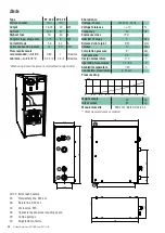
Страница 20: ...ure class IP x1 Number of steps 7 step Screwed cable joint 37 mm Volume 17 litres Calculation pressure 4 bar Test pressure 5 7 bar Design temperature 110 C Operating temperature 20 95 C Ambient temper...

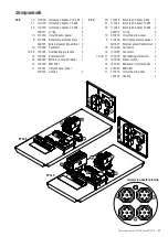
Страница 21: ...rcuit breaker 1 13 218020 EMI filter 11 210221 Circuit board panel 700414 Overlay 1 42 E 20 110016 Immersion heater 6 kW 1 21 110044 Immersion heater 12 kW 1 22 110044 Immersion heater 12 kW 2 300017...

Страница 22: ...ectable via Menu Advanced Service level rows 16 17 At overtemperature the connected output steps out and steps in again only when the temperature has dropped below the limit Low boiler temperature Yel...

Страница 23: ...temperature sensor The sensor must not be connected to the circuit board during resistance measurement When the boiler is energized voltage is measured in the sensor s connection points at the PCB Bo...

Страница 24: ...V rmebaronen AB Arkelstorpsv gen 88 SE 291 94 Kristianstad Tel 46 44 22 63 20 www varmebaronen se www varmebaronen com info varmebaronen se...

Отзывы: