VarioCooking Center WHITEFICIENCY Series Скачать руководство пользователя страница 1

Original technical instructions

ATTENTION: 

Please read this manual carefully before working on the equipment.


Содержание WHITEFICIENCY Series

Страница 1: ...Original technical instructions ATTENTION Please read this manual carefully before working on the equipment...

Страница 2: ...v03 July 2016 Hen I 02...

Страница 3: ...unit must be disconnected from any electrical power source Information The products explained in this manual are subject to changes both technically and user level Their description cannot in anyway...

Страница 4: ...ic diagram VI 02 Overview of the boards VI 12 SD card VI 13 Boards VI 16 Power supply module VII 01 Safety chain VII 02 Low voltage VII 12 Hydraulic circuit Module VIII 01 Hydraulic circuit VIII 03 He...

Страница 5: ...ooking XI 08 Description of the 3 stages of the process XI 10 Cooking mode module XII 01 Safety note XII 02 Boiling mode XII 03 Basket boiling mode XII 04 Frying mode XII 05 Deep frying mode XII 06 Ba...

Страница 6: ...Contents GB v03 July 2016 Hen...

Страница 7: ...General instructions II 02 Instructions and symbols II 02 Guarantee and disclaimer Product information II 03 Title block Technical Support Abbreviations II 04 Introduction Chapter Page...

Страница 8: ...ot to be excluded No reproduction of the content of this manual in other electronic or printed publications is permitted without our written agreement Symbols used Danger Danger Indicates a high level...

Страница 9: ...l modifications of the equipment The equipment used despite a fault being dis played or the appearance of a fault Non compliant repairs use of non original spare parts Product information Manufacturer...

Страница 10: ...design Designer Whether technical support is required During any failure if you wish to contact our technical service you will be asked for the following information Type Serial number Software versi...

Страница 11: ...II 05 v03 July 2016 Hen Introduction Line Units Serial number starting from Sw Revision VCCM VCCWE All...

Страница 12: ...Preamble GB v03 July 2016 Hen...

Страница 13: ...User mode Module Chapter Page General Description III 02 Control panel III 02 General information III 03 Menu description III 04 My VCC menu III 04 Help menu III 08 Preconditions and warnings III 09...

Страница 14: ...cription Control panel A On off button B 8 inch TFT touchscreen C Dial and function selector III 02 v03 July 2016 Hen User mode Module Line Appliances Serial number starting from Sw Revision VCCM VCCW...

Страница 15: ...revious menu Function key Access to the controls for parts of the appliance Tipping pan filling with water drain pan power to the ceramic hob Flashing A red frame flashing around a button tells you th...

Страница 16: ...emperature unit Celsius or Fahrenheit Setting the system sounds Sounds Adjusting the master volume Enable or disable the Key tone Volume of key tone Setting the melody loudness and duration when an ac...

Страница 17: ...t user profiles Import user profiles Export baking programs customized pictures Import baking programs customized pictures Deleting all customized pictures Appliance IP address Network Configuration D...

Страница 18: ...ay before diming of the display Adjust standby time after preheating Param tres expert Programming a delayed start MyDisplay User profil activation Personnalisation des menus utilisateur Edit Profile...

Страница 19: ...l phone pour la Hotline chef Param trage du num ro de t l phone du service technique Choix du mode de l appareil 4 modes possibles voir chapitre Description du mode service pour de plus amples d tail...

Страница 20: ...de To access this function press the button to start the help menu when you need it Start the help menu Access to the selected help manual menu Back to the previous chapter Navigate to the previous pa...

Страница 21: ...own Lifting the basket The previous AutoLiftTM function has not fully raised the cover Tipping the pan required This precondition is always asked for af ter a frying mode This in order to empty the oi...

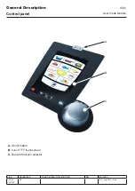
Страница 22: ...User mode module GB v03 July 2016 Hen...

Страница 23: ...s IV 06 Diagnosis sensors IV 08 Diagnosis pressure IV 10 Diagnosis real time measurements operating time IV 12 Diagnosis statistics service messages IV 13 Diagnosis service message history IV 14 Funct...

Страница 24: ...IV 02 v03 July 2016 Hen Service Mode Module I n t e n t i o n a l l y l e f t b l a n k...

Страница 25: ...avigate between the service mode and user mode with the special button only available in the diagnosis menu from the service mode Once you are in user mode you have five minutes to return to service m...

Страница 26: ...me of different cooking modes Heating Heating zones and hob Service message statistics List of all messages from ser vices with times Service message history List of the last 15 messages with full det...

Страница 27: ...r the ceramic hob Movements Activating the actuators or motors Solenoid valves Activation of solenoid valves Allocation Allocation of thermocouples to heating zones Calibration Calibration of all ther...

Страница 28: ...All Buttons Selection of a row in the table Probes on the right Probe Use Unit B2 Pan temperature 112 112T B7 Temperature R4 211 311 B8 Temperature R5 211 311 B9 Temperature R6 211 311 B10 Temperature...

Страница 29: ...ffset values calculated during the last calibration B4 B17 200 6000 without unit since soft 01 01 01 3 500 6000 without unit before soft 01 01 01 3 B12 1 B13 6 3 3 C B1 or B2 3 7 C Max Temp Maximum te...

Страница 30: ...Limit switch S18 cover unlocked 112P Cover locked Limit switch S19 cover locked 112P Pan valve Microswitch S20 posi tion pan valve 112 112T 112L Pan down Limit switch S26 pan down 112T Pan up Limit s...

Страница 31: ...hot water option Hot water Solenoid valve Y7 All hot water option Columns displayed Name Explanation Details Status Status of the solenoid valve Open or closed Volume Amount of water counted since th...

Страница 32: ...6 Handle 112P 211P 311P Heating Indicates whether or not the heating is active 112P Pressure on the right P2 Column Use Unit Code Pressure sensor P2 112P Absolute Absolute pressure value hectopascals...

Страница 33: ...pressure machine Stand by Preheating Regulation Decompression Error 112P 211P 311P Statuses right side Use Unit Unlocked Status of limit switch S18 112P Locked Status of limit switch S7 112P Pressure...

Страница 34: ...lies are as follows Components All motors Solenoid valves All solenoid valves Modes Usage time of different cooking modes Also included is the overall time the unit operates Heating Operating time for...

Страница 35: ...ed out at the same time Columns displayed Name Explanation Details Message number See the service messages chapter for more details Counter Number of occurrences of that mes sage First occurrence Date...

Страница 36: ...Name Explanation Details Sequential number Service Message number See the service messages chapter for more details First occurrence Date of the first appearance of the service message Counter Number...

Страница 37: ...nit can cause damage or injury The module is divided into 3 groups Heating Movement Solenoid valve 112 112T the function test is only active for the side of the unit selected in user mode v03 July 201...

Страница 38: ...an to the corresponding thermocouple You will find a detailed description of this function in the chapter Heating Allocation The process is automated and must not be interrupted v03 July 2016 Hen IV 1...

Страница 39: ...function in the chapter Heating Calibration The process is automated and must not be interrupted Attention The unit s installation altitude must be correctly set before you calibrate it If you do not...

Страница 40: ...iate be subject to allocation and calibration Procedure A Get in touch with the manufacturer or his legal representative making sure you have the following information The unit key Fig 1 The unit s se...

Страница 41: ...t it if necessary Fig 3 D Confirm by pressing the validation button Fig 3 E Restart the unit Fig 4 Allocation and calibration are not necessary after adding an option hob fryer or energy optimiser v03...

Страница 42: ...ge is displayed ON The unit no longer heats or fills with water movements are disabled No service message is displayed DUMMY This special mode is reserved for dummy operation The unit no longer heats...

Страница 43: ...IV 21 v03 July 2016 Hen Service Mode Module Line Units Serial number starting from Sw Revision VCCM VCCWE All ExxXH1009xxxxxxx 01 00 08...

Страница 44: ...Service mode module GB v03 July 2016 Hen...

Страница 45: ...V 05 Service data Description V 06 Updating the USB stick VCC Loader V 13 Updating the unit software alternative 1 V 14 Updating the unit software alternative 2 V 15 Ethernet V 16 General network inf...

Страница 46: ...v03 July 2016 Hen V 02 Communication Module...

Страница 47: ...lications The USB port can be used for various purposes A Download cooking programs from the unit to a USB stick B Upload cooking programs from a USB stick to the unit C Download general information d...

Страница 48: ...e even longer and be even larger E Start the download by pressing the HACCP button F The download has successfully finished when the green tick is displayed G If the download is not successful the USB...

Страница 49: ...he INFO button D Select the beginning and end dates of the data to be downloaded You can take up to 10 days data guaranteed Depending how the unit is used you can take even more but the download will...

Страница 50: ...time is in the format HHMMSS xxxx represents the service or history file The file whose name ends in service contains all the service mode information The file ending with history contains the history...

Страница 51: ...llocation Calibration Date Time Date and time of the last calibration Calibration pressure Pressure measured during the last calibration Config section This contains the unit s configuration informati...

Страница 52: ...ervice message Factory setting Chef line phone Phone number displayed to the cus tomer Chef menu Factory setting Flowmeter Flowmeter VarioDose setting 900 1150 Diagnostic section Diag 1 This contains...

Страница 53: ...formation on the sensors see the components chapter Field name Translation Note Sensor Actor Sensor actuator Internal use Date Time Date and time of recording Operating time section RT1 This contains...

Страница 54: ...erature of the shaft of the core probe B12 6 or B13 6 Pan temperature Pan temperature B1 or B2 Pan temp max Max pan temperature B1 or B2 Pan temp max date Time Date and time of recording the maxi mum...

Страница 55: ...rence date time Counter Last occurrence date time Software version history section SW Histo This contains the history of the software versions that have been flashed onto the unit Only the last ten ve...

Страница 56: ...USB v03 July 2016 Hen V 12 Communication Module Line Units Serial number starting from Sw Revision VCCM VCCWE...

Страница 57: ...USB stick An internet connection is required Run the file VCCLoaderStarter exe I During start up the program checks if there is a new version available on our servers II If your files need to be upda...

Страница 58: ...atic the process may in the worst case take up to 15 minutes The TFT screen may stay black during this time but the unit will emit a repetitive sound D Wait for the main menu to appear before disconne...

Страница 59: ...ake up to 15 minutes The TFT screen may go black during this time However the unit will emit a repetitive sound C Wait for the the main menu to appear before disconnecting the USB stick D Check if the...

Страница 60: ...on the left which refers to the network It is called the network ID netID The numbers on the right refer to computers on that network It is called the host ID host ID For a better understanding we can...

Страница 61: ...t a VarioCooking Center directly to a computer In this case leave the VarioCooking Center s gateway setting empty This information will also be given to you by the network administrator Ethernet optio...

Страница 62: ...st be routed with the control cable C For model 112T there is a location for connecting the connection kit If the units are built with this option you will find the connector as shown in figure C D Fo...

Страница 63: ...n the communication menu select the IP address settings menu C Set in turn the IP address the subnet mask and the gateway address The IP address settings will be given to you by your local network adm...

Страница 64: ...Communication Module GB v03 July 2016 Hen...

Страница 65: ...112T up to index I VI 06 VarioCooking Center 112T 112L from index J VI 08 VarioCooking Center 211 311 VI 10 Overview of the boards VI 12 VarioCooking Center 112 112T 211 311 VI 12 SD card VI 13 Descri...

Страница 66: ...Schematic diagram VarioCooking Center 112P up to index H v03 July 2016 Hen VI 02 Control Module Line Units Serial number starting from Sw Revision VCCM VCCWE 112 112P E11XH1009xxxxxxx...

Страница 67: ...1 F12 Pressure switch 2 0kPa 20 mbar F13 F17 F19 Safety thermostat 355 C heating zone F20 F22 F25 Safety thermostat VarioDose 130 C F26 P1 Pressure sensor P2 PT 1 Pan position potentiometer PT 2 M2 Pa...

Страница 68: ...Schematic diagram VarioCooking Center 112P from index J v03 July 2016 Hen VI 04 Control Module Line Units Serial number starting from Sw Revision VCCM VCCWE 112 112P E11VJ1412xxxxxxx E11PJ1412xxxxxxx...

Страница 69: ...ssure switch 2 0kPa 20 mbar F13 F17 F19 Safety thermostat 355 C heating zone F20 F22 F25 Safety thermostat VarioDose 130 C F26 P1 Pressure sensor P2 PT 1 Pan and AutoLift position potentiometer PT 2 M...

Страница 70: ...Schematic diagram VarioCooking Center 112T up to index I v03 July 2016 Hen VI 06 Control Module Line Units Serial number starting from Sw Revision VCCM VCCWE 112T E12VI1310xxxxxxx...

Страница 71: ...1 B13 6 F6 Safety thermostat 205 C F10 F17 F19 Safety thermostat 355 C heating zone F20 F22 F25 Safety thermostat VarioDose 130 C F26 M2 Pan tilting and AutoLift actuator M6 S8 Pan valve position micr...

Страница 72: ...ematic diagram VarioCooking Center 112T 112L from index J v03 July 2016 Hen VI 08 Control Module Line Units Serial number starting from Sw Revision VCCM VCCWE 112T 112L E12VJ1412xxxxxxx E13VJ1509xxxxx...

Страница 73: ...thermocouple B13 1 B13 6 F6 Safety thermostat 205 C F10 F17 F19 Safety thermostat 355 C heating zone 1112T F20 F22 F17 F22 Safety thermostat 355 C heating zone 1112L F23 F24 F27 F30 F25 Safety thermo...

Страница 74: ...VarioCooking Center 211 311 v03 July 2016 Hen VI 10 Control Module Line Units Serial number starting from Sw Revision VCCM VCCWE 211 311 211P 311P E21VH1009xxxxxxx E21PH11009xxxxxxx E31VH1110xxxxxxx...

Страница 75: ...ch 2 0kPa 20 mbar F17 F24 Safety thermostat 355 C heating zone F25 Safety thermostat VarioDose 130 C P1 Pressure sensor PT 1 Pan position potentiometer PT 2 Lid position Potentiometer M2 Pan tilting a...

Страница 76: ...Overview of the boards VarioCooking Center 112 112T 211 311 v03 July 2016 Hen VI 12 Control Module Line Units Serial number starting from Sw Revision VCCM VCCWE All ExxVH1009xxxxxxx...

Страница 77: ...unit either The types of units The serial number The list of options Ceramic hob Pressure Fryer Energy optimization connection capability Hot water Attention each SD card belongs to its unit do not ex...

Страница 78: ...llocation and calibration of the heating zones is now mandatory It is advisable to remove the USB stick from the unit with the power off Exchange of the SD card new Main Board A2 remains already used...

Страница 79: ...ar The allocation and calibration of the heating zones is now mandatory It is advisable to remove the USB stick from the unit with the power off Exchange of the Main Board A2 card and the SD card Both...

Страница 80: ...that the processor is in Reset A4 board explanation of the statuses of the different LEDs Fig B LED 1 green Indicates 11 5 VAC is present LED 4 Orange Indicates a transmission problem on the bus towar...

Страница 81: ...v03 July 2016 Hen VI 17 Control Module Line Units Serial number starting from Sw Revision VCCM VCCWE...

Страница 82: ...Control Module GB v03 July 2016 Hen...

Страница 83: ...to 2013 04 VII 05 Components from 2013 05 VII 06 Unit 112 from 2013 05 VII 08 Unit 112T from 2013 12 VII 09 Unit 112L from 2015 09 VII 10 Units 211 311 from 2013 05 VII 11 Low voltage VII 12 Power sup...

Страница 84: ...unit in an emergency Each of its components has the ability to entirely stop the unit by acting on the main switch Components up to 2013 04 VII 02 v03 July 2016 Hen Power supply module Line Units Ser...

Страница 85: ...t for overheating oil manual reset F8 Differential switch 30 mA F7 F11 High pressure switch 200 mbar with automatic reset MMi board Power button VII 03 v03 July 2016 Hen Power supply module Line Units...

Страница 86: ...Safety chain Unit 112 up to 2013 04 VII 04 v03 July 2016 Hen Power supply module Line Units Serial number starting from Sw Revision VCCM VCCWE 112 112P E11xH1009xxxxxxx...

Страница 87: ...Safety chain Units 211 311 up to 2013 04 VII 05 v03 July 2016 Hen Power supply module Line Units Serial number starting from Sw Revision VCCM VCCWE 211 311 211P 311P E21xH1009xxxxxxx E31xH1009xxxxxxx...

Страница 88: ...y reset VII 06 v03 July 2016 Hen Power supply module F1 F2 0 1 MMi A1 K1 F6 112 205 C 211 311 215 C 112 F7 F11 211 311 F7 200mbar Line Units Serial number starting from Sw Revision VCCM VCCWE All E11x...

Страница 89: ...l reset F17 F30 Safety thermostat for heating zone overheating with automatic reset F7 F11 Safety high pressure switch 200 mbar with automatic reset MMi Power button VII 07 v03 July 2016 Hen Power sup...

Страница 90: ...Safety chain Unit 112 from 2013 05 VII 08 v03 July 2016 Hen Power supply module Line Units Serial number starting from Sw Revision VCCM VCCWE 112 E11xH1305xxxxxxx...

Страница 91: ...Safety chain Unit 112T from 2013 12 VII 09 v03 July 2016 Hen Power supply module Line Units Serial number starting from Sw Revision VCCM VCCWE 112T E12VI1312xxxxxxx...

Страница 92: ...Safety chain Unit 112L from 2015 09 VII 10 v03 July 2016 Hen Power supply module Ligne Appareils Num ro de s rie A partir de Sw R vision VCCM VCCWE 112L E13VJ1509xxxxxxx...

Страница 93: ...Safety chain Units 211 311 from 2013 05 VII 11 v03 July 2016 Hen Power supply module Line Units Serial number starting from Sw Revision VCCM VCCWE 211 311 E21xH1305xxxxxxx E31xH1305xxxxxxx...

Страница 94: ...VAC T4 Transformer for power for controlling units with special voltages 3AC400 445V A2 Main Board A4 Temperature control board A1 MMi board TFT Display screen VII 12 v03 July 2016 Hen Power supply mo...

Страница 95: ...4 VDC T4 Transformer as power adapter for special voltages units 3AC400 445V A5 X relay board distribution of power to the cylinders M2 M3 M4 M6 M7 M8 Actuators VII 13 v03 July 2016 Hen Power supply m...

Страница 96: ...Power supply module GB v03 July 2016 Hen...

Страница 97: ...T 112L without hot water VIII 04 112 V 112 P with hot water VIII 05 211 311 V and P without hot water index H and I VIII 06 211 311 V and P with hot water until index H VIII 07 211 311 V and P with ho...

Страница 98: ...VIII 02 v03 July 2016 Hen Hydraulic circuit Module I n t e n t i o n a l l y l e f t b l a n k...

Страница 99: ...the specified tolerances the output signal of the flow meter varies The number of pulses corresponding to a unit of water is adjustable in service mode Service mode Basic settings VarioDose Oil protec...

Страница 100: ...d valve VarioDose Flowmeter Model 112 P Fig B Label Description Y1 Left pan fill solenoid valve Y2 Solenoid valve control box Y3 Right pan fill solenoid valve VarioDose Flowmeter v03 July 2016 Hen VII...

Страница 101: ...solenoid valve VarioDose Flowmeter Model 112 P Fig B Label Description Y1 Left pan fill solenoid valve Y2 Solenoid valve control box Y3 Right pan fill solenoid valve Y6 Cold water solenoid valve Y7 H...

Страница 102: ...olenoid valve VarioDose Flowmeter Model 211 311 P Fig B Label Description Y1 Left pan fill solenoid valve Y2 Solenoid valve control box VarioDose Flowmeter v03 July 2016 Hen VIII 06 Hydraulic circuit...

Страница 103: ...enoid valve VarioDose Flowmeter Model 211 311 P Fig B Label Description Y1 Left pan fill solenoid valve Y2 Solenoid valve control box Y6 Cold water solenoid valve Y7 Hot water solenoid valve VarioDose...

Страница 104: ...oid valve VarioDose Flowmeter Model 211 311 P Fig B Label Description Y1 Cold water solenoid valve Y2 Solenoid valve control box Y7 Hot water solenoid valve VarioDose Flowmeter v03 July 2016 Hen VIII...

Страница 105: ...VIII 09 v03 July 2016 Hen Hydraulic circuit Module Ligne Appareils Num ro de s rie A partir de Sw R vision VCCM VCCWE...

Страница 106: ...Hydraulic circuit module GB v03 July 2016 Hen...

Страница 107: ...st overheating IX 07 Ceramic hob IX 08 Components and description IX 08 Option Energy optimizer IX 09 Allocation IX 10 Description IX 10 Practical guide IX 11 Instructions and Error codes IX 12 Calibr...

Страница 108: ...lement D Support washer E Safety thermostat Bimetal 355 C F Thermocouple support G Thermocouple H Mounting nut Installation of the heating unit Fig 1 IX 02 v03 July 2016 Hen Heating system module Line...

Страница 109: ...torque of 4 Nm Fig 3 Read the installation instructions supplied with the kit carefully The heating element must be in contact with the bottom of the pan via the graphite sheet The thermocouple must...

Страница 110: ...R5 B8 R6 B9 Fig 2 VCC 112L Side Heating zone Thermocouple Left R1 B4 R2 B5 R3 B6 R4 B7 R5 B8 R6 B9 Right R7 B10 R8 B11 R9 B14 R10 B15 R11 B16 R12 B17 Fig 2 3 VDC 211 311 Heating zone Thermocouple R1 B...

Страница 111: ...ing to the voltage Dynamic Hardware 112 112T 211 311 3NAC400V 3NAC415V 445V 445V Dynamic Software 112L 3NAC400V 3NAC415V 3AC200V 230V 230V 200V For connection values refer to the installation manual D...

Страница 112: ...B12 B13 C Main Board A2 D Regulation board A4 E Main switch K1 F SSR V1 V6 G Heater overheating safety device 355 C F17 F24 H Pan overheating safety device 205 215 C F6 F10 I Heating element R1 R8 IX...

Страница 113: ...service mode should be checked first in the Measurements chapter in real time The fact that our units are fitted with a differential switch does exempt you from installing differential protection in t...

Страница 114: ...te 2 2 Ceramic heating element Relationship time basis power Level of heating Active heating seconds Inactive heating seconds 1 1 5 2 2 4 3 3 3 4 4 2 5 5 1 6 6 0 Safety Overheating safety is provided...

Страница 115: ...Connectors Connector Description X20 1 230 VAC Neutral from the VarioCooking Center X20 2 230 VAC Heating allowance from the energy optimizer X20 3 230 VAC Information unit is switched on from the Va...

Страница 116: ...at reacted to the change in temperature The thermocouple it finds is then associated with the heating zone When should an allocation be carried out This operation is not necessary after each intervent...

Страница 117: ...ending on the model 112 211 or 311 It is interrupted when an anomaly occurs with the corresponding error code being displayed See following pages Description of the automatic sequence I Heat up a zone...

Страница 118: ...re displayed The active heating element as well as the number of the connector electronic board A4 allocated to the thermocouple From software version 01 00 12 this information remains displayed even...

Страница 119: ...ecorresponding board Energy optimisation system Sicotronic Fault with a heater faulty wiring Error 15 Thermocouple already assigned Two heating zones are definitely active at the same time check the w...

Страница 120: ...card 42 00 128 The I O board A4 42 00 159F One or more thermocouples A core probe One or more heaters whichever ones they are Always After an allocation operation If the cook complains of irregularity...

Страница 121: ...tomatic process lasts between 15 and 30 minutes depending on the model and the initial temperature of the water It is interrupted when an anomaly occurs with an error code being displayed see followin...

Страница 122: ...ed Calibration successfully completed NB For more information about the service mode and the calibration module see the Service Mode chapter For 112L Dynamic units each pan is calibrated separately Re...

Страница 123: ...multaneously 4B Left pan only 4C Right pan only Etape 1 Connection test t 5 sec E 40 Heating zone thermocouple E 28 27 Core sensor thermocouple E 26 25 Pan thermocouple E 38 Time out E 36 Heating zone...

Страница 124: ...nnect the USB stick to the unit B Go to the communication menu then USB C Start the download by pressing the INFO button D Select the beginning and end dates of the data to be downloaded You can take...

Страница 125: ...download Example of the content of the LOG carpet LOG after service data download Content of the log file Calibration full start and end date Description of the result of each step Remaining time in...

Страница 126: ...emperature measured 200 C Water present Broken thermocouple PCB board malfunction SSR malfunction Error 33 Heating zone calibration result outside tolerances 200 6000 Check which thermocouple Service...

Страница 127: ...offset temperature of the right pan B2 is not within the tolerances 3 C 7 C Altitude setting Check the thermocouple for good contact with pan bottom For pressure units only Check for correct function...

Страница 128: ...Heating Module GB v03 July 2016 Hen...

Страница 129: ...X 12 VCC 112T Control of movements principle X 13 VCC 112 Components and identification X 14 VCC 112 Control of movements principle X 15 Pan tilting operation M2 M6 X 16 AutoLift TM tilting operation...

Страница 130: ...iption of the pan lid tilting actuator X 30 Components X 32 Lid lock 1st generation actuator X 33 Torque limiter Index H units X 34 Lid lock 2nd generation actuator X 36 Lid lock 3rd generation actuat...

Страница 131: ...X 03 v03 July 2016 Hen Motorisation Module I n t e n t i o n a l l y l e f t b l a n k Line Units Serial number starting from Sw Revision VCCM VCCWE...

Страница 132: ...switch S10 Left Autolift up limit switch Right M6 Right tilting actuator S26 Right pan down limit switch S28 Right pan up limit switch S12 Right Autolift up limit switch Components X 04 v03 July 2016...

Страница 133: ...X129 1 Right Pan X24 1 2 X13 1 2 X131 1 2 X24 1 2 3 4 X13 1 2 X131 1 2 Autolift Lid X24 1 2 5 6 X13 1 2 X131 2 X132 1 X24 1 2 3 4 5 6 X13 1 2 X131 2 X132 1 Wiring Summary table of limit switch states...

Страница 134: ...mit switches Internal components of the motor no information feedback to electronics Left pan Right pan Mechanics of the tilting system X 06 v03 July 2016 Hen Motorisation Module Line Units Serial num...

Страница 135: ...VCC 112T index I X 07 v03 July 2016 Hen Motorisation Module Line Units Serial number starting from Sw Revision VCCM VCCWE I n t e n t i o n a l l y l e f t b l a n k...

Страница 136: ...2 M6 Positions of the actuator States of the sensors Pan down Pan up 0 1 Visible state as in the service pack X 08 v03 July 2016 Hen Motorisation Module Line Units Serial number starting from Sw Revis...

Страница 137: ...T index I Pan tilting operation M2 M6 Supply voltage Descent of pan Rise of pan X 09 v03 July 2016 Hen Motorisation Module Line Units Serial number starting from Sw Revision VCCM VCCWE 112T E12VI1310x...

Страница 138: ...6 Positions of the actuator States of the sensors AutoLiftTM up AutoLiftTM down 0 1 Visible state as in the service pack X 10 v03 July 2016 Hen Motorisation Module Line Units Serial number starting fr...

Страница 139: ...I AutoLiftTM tilting operation M2 M6 Supply voltage Raise AutoLiftTM Lower AutoLiftTM X 11 v03 July 2016 Hen Motorisation Module Line Units Serial number starting from Sw Revision VCCM VCCWE 112T E12...

Страница 140: ...r M2 S10 Left AutoLift up limit switch Right M6 Right tilting actuator PT2 potentiometer of motor M6 S10 Right Autolift up limit switch Components X 12 v03 July 2016 Hen Motorisation Module Line Units...

Страница 141: ...9 1 Right Pan X24 1 2 X13 1 2 X131 1 2 X24 1 2 3 4 X13 1 2 X131 1 2 Autolift Lid X24 1 2 5 6 X13 1 2 X131 2 X132 1 X24 1 2 3 4 5 6 X13 1 2 X131 2 X132 1 Wiring Summary table of states of limit switch...

Страница 142: ...t M6 Right tilting actuator PT2 potentiometer of motor M6 S10 Right Autolift up limit switch S13 Right lid closed limit switch Pressure devices only M8 right locking actuator Summary table of states o...

Страница 143: ...29 1 X24 1 2 3 4 5 6 X128 2 X129 1 Lock lid X24 1 2 5 6 7 8 X130 1 2 X24 1 2 3 4 5 6 7 8 X130 1 2 Right Pan X24 1 2 X13 1 2 X131 1 2 X24 1 2 3 4 X13 1 2 X131 1 2 Autolift Lid X24 1 2 5 6 X13 1 2 X131...

Страница 144: ...tion M2 M6 Positions of the actuator States of the sensors Pan down Pan up X 16 v03 July 2016 Hen Motorisation Module Line Units Serial number starting from Sw Revision VCCM VCCWE 112 112T 112L E11xJ1...

Страница 145: ...n M2 M6 Positions of the actuator States of the sensors AutoLiftTM up AutoLiftTM down X 17 v03 July 2016 Hen Motorisation Module Line Units Serial number starting from Sw Revision VCCM VCCWE 112 112T...

Страница 146: ...dentification of the actuators Components X 18 v03 July 2016 Hen Motorisation Module Line Units Serial number starting from Sw Revision VCCM VCCWE 112 E11xH1009xxxxxxx TOUCH TFT A1 MMi A2 Main Board P...

Страница 147: ...24 1 2 3 4 5 6 X129 1 2 Lock Lid X24 1 2 5 6 7 8 X130 1 2 X24 1 2 3 4 5 6 7 8 X130 1 2 Right Pan X24 1 2 X13 1 2 X131 1 2 X24 1 2 3 4 X13 1 2 X131 1 2 Autolift Lid X24 1 2 5 6 X13 1 2 X132 1 2 X24 1 2...

Страница 148: ...d G Measurement potentiometer H Safety cam Maximum length of rod Positions Fig 2 Down position determined by contact with the rear chute Clutch protects the motor Down position recognised if digital v...

Страница 149: ...tch no feedback to the electronics Never completely lower the lid when it is in AutoLift low position Down position of the lid Pressure unit ExxP only to allow the lid to be locked Detection via limit...

Страница 150: ...ower supply 24 VDC No internal limit switches to inform electronics Only the up position of the AutoLift is recognised by S10 S12 Lock the lid on pressure equipment Role of the pressure switch F12 F13...

Страница 151: ...d limit switch S6 S7 or S18 S19 right hand lid C Limit switch connectors S6 S7 or S18 S19 right hand lid D Motor 24 VDC connectors Attention to the wiring of the pressure switch F12 or F13 He will all...

Страница 152: ...r for motor M2 M3 Lid tilting actuator PT2 potentiometer of motor M3 M4 Lid lock actuator S6 S7 limit switch motor M4 Components X 24 v03 July 2016 Hen Motorisation Module Line Units Serial number sta...

Страница 153: ...VDC Left Pan X24 1 2 X128 1 2 X24 1 2 3 4 X128 1 2 Autolift Lid X24 1 2 5 6 X129 1 2 X24 1 2 3 4 5 6 X129 1 2 Lock Lid X24 1 2 5 6 7 8 X130 1 2 X24 1 2 3 4 5 6 7 8 X130 1 2 Wiring X 25 v03 July 2016...

Страница 154: ...ossible if the lid is not detected in the upper position No lid movement is possible before the pan registers his zero A Motor 24 VDC B Thermal safety 90 C C Mechanism including a friction clutch syst...

Страница 155: ...VCC 211 311 X 27 v03 July 2016 Hen Motorisation Module Line Units Serial number starting from Sw Revision VCCM VCCWE...

Страница 156: ...motor Down position recognised if digital value between 0 and 100 only Up position Up position determined by reading the poten tiometer Safety via limit switches built into the motor Conditions to al...

Страница 157: ...s the motor Down position determined if digital value between 0 and 100 only Up position Up position determined by reading the poten tiometer Safety via limit switches built into the motor Conditions...

Страница 158: ...ator do it electrically use the function test from the service mode No pan movement is possible if the lid is not detected in the upper position No lid movement is possible before the pan registers hi...

Страница 159: ...rsion 01 01 00 the posi tion recognized by the unit is indicated in the Diagnostic Real time measurement As for the lower position the upper position is calculated from the value delivered by the po t...

Страница 160: ...he diode Unlock Fig 4 The power to the actuator for unlocking must go through the pressure switch F12 X 32 v03 July 2016 Hen Motorisation Module Line Units Serial number starting from Sw Revision VCCM...

Страница 161: ...and Phoenix Mecano In series since 2005 05 up to 2012 04 Attention to the wiring of the pressure switch F12 for unlocking only if pressure is lower than 20 mbar while locking is still possible See pag...

Страница 162: ...ly to the unlocking motor If the power supply is greater than 2A to the unlocking motor M4 the torque limiter stops the power to the actuator Components Wiring X 34 v03 July 2016 Hen Motorisation Modu...

Страница 163: ...X 35 v03 July 2016 Hen Motorisation Module Line Units Serial number starting from Sw Revision VCCM VCCWE...

Страница 164: ...lever D Front locking hook E Rear locking hook Features Ref 24 02 533 Motor actuator 24 VDC Brand Phoenix Mecano In series since 2012 04 up to 2012 05 Careful with the wiring of the pressure switch F1...

Страница 165: ...and actuating lever D Front locking hook E Rear locking hook Features Ref 24 02 689 Motor actuator 24 VDC Brand Linak In series from 2012 05 Careful with the wiring of the pressure switch F12 for unl...

Страница 166: ...T B1 120 C Frying mode inactive Closing X11 3 4 S8 0 Right Opening X25 7 8 S20 1 T B2 120 C Frying mode inactive Closing X25 7 8 S20 0 X 38 v03 July 2016 Hen Motorisation Module Line Units Serial numb...

Страница 167: ...the micro switch Status of the pan valve S8 Left side S20 Right side Closed 0 0 In motion 0 or 1 0 or 1 Open 1 1 C Detail of the cam micro switch system D Traction cable Relationship cam motor Status...

Страница 168: ...X 40 v03 July 2016 Hen Motorisation Module Line Units Serial number starting from Sw Revision VCCM VCCWE...

Страница 169: ...v03 July 2016 Hen Motorisation Module X 41 Line Units Serial number starting from Sw Revision VCCM VCCWE...

Страница 170: ...Motorisation Module GB v03 July 2016 Hen...

Страница 171: ...s 211 311 XI 06 Diagram XI 06 List of components XI 07 Pressure Cooking XI 08 General Pressure components XI 08 Description General XI 09 Description of the 3 stages of the process XI 10 Preconditions...

Страница 172: ...XI 02 v03 July 2016 Hen Pressure Module Line Units Serial number starting from Sw Revision VCCM VCCWE...

Страница 173: ...the unit in pressure mode is possible only if The pressure circuit is clean The core probe is in good working condition no measuring point is defective The pan thermocouple is in good working conditio...

Страница 174: ...Pressure circuit models 112 Diagram XI 04 v03 July 2016 Hen Pressure Module Line Units Serial number starting from Sw Revision VCCM VCCWE 112P E11PH1009xxxxxxx F7 F11 F12 F13 P1 Y4 Y2 P2 Y5 A A B C R...

Страница 175: ...sure sensor P1 P2 Output signal from 0 to 5 VDC Decompression solenoid valve Y4 Y5 Solenoid valve normally open Control box solenoid valve Y2 Maximum temperature of water 25 C Pressure measuring nozzl...

Страница 176: ...circuit models 211 311 Diagram Diagram XI 06 v03 July 2016 Hen Pressure Module Line Units Serial number starting from Sw Revision VCCM VCCWE 211P 311 P E21PH1009xxxxxxx E31PH1009xxxxxxx F7 F11 P1 Y4 Y...

Страница 177: ...er Pressure sensor P1 Output signal from 0 to 5 VDC Decompression solenoid valve Y4 Solenoid valve normally open Control box solenoid valve Y2 Maximum temperature of water 25 C Pressure measuring nozz...

Страница 178: ...General Pressure components XI 08 v03 July 2016 Hen Pressure Module Line Units Serial number starting from Sw Revision VCCM VCCWE 112P 211P 311P ExxPH1009xxxxxxx CONTROL SOFT SAFETY 200 mbar SAFETY 2...

Страница 179: ...more detail on the 3 steps of the pressure mode on the next page Important points to observe A The height of the load in the pan Marked 14L in a model 112 Marked 80L in a model 211 Marked 100L in a m...

Страница 180: ...over lock Cover must be detected in the down position L S11 1 R S13 1 D Cover must be locked VCC112P L S7 1 VCC112P R S19 1 VCC211 311 S7 S21 1 One of the safety features of the pressure mode is also...

Страница 181: ...F12 R F13 does not allow unlocking while P 20 mbar B Security release Prevent unlocking the unit Unauthorised unlock if P 25 mbar L P1 R P2 or T c T c boiling 20 C L B12 B1 R B13 B2 C Preheating safe...

Страница 182: ...mbar L F7 R F11 cut off the appliance via K1 B Overheating safety device Avoid overpressure Decompression solenoid valve L Y4 R Y5 opens if P 170 mbar L P1 R P2 Closes as soon as P 150 mbar C Overhea...

Страница 183: ...utton displayed Minimum waiting time set to 3 min Display of the button only if P 25 mbar 3 minutes L P1 R P2 OR T C T boiling L B12 B1 R B13 B2 AND P 20 mbar L P1 R P2 C Hardware unlocking safety dev...

Страница 184: ...nds to this pressure in the pan Different pressures displayed in the service mode Absolute P atmospheric P 1000 mbar Absolute P 1150 mbar 150 mbar Reference P 1000 mbar No pressure mode in progress Co...

Страница 185: ...XI 15 v03 July 2016 Hen Pressure Module Line Units Serial number starting from Sw Revision VCCM VCCWE 01 01 00...

Страница 186: ...Pressure Module GB v03 July 2016 Hen...

Страница 187: ...Safety note XII 02 Boiling mode XII 03 Basket boiling mode XII 04 Frying mode XII 05 Deep frying mode XII 06 Basket deep frying mode XII 07 Cooking mode module Chapter Page...

Страница 188: ...is possible only if The core probe is in good working condition no measuring point is defective The pan thermocouple is in good working condition Never bypass a safety device do not change the safety...

Страница 189: ...rature C Regulation lid closed If the lid is no longer detected in the up position then the maximum temperature T boiling 3 C Via pan thermocouple L B1 R B2 or core probe L B12 R B13 Same conditions f...

Страница 190: ...mperature The user must validate the descent of the basket D Regulation Regulation via Pan thermocouple L B1 R B2 or core probe L B12 R B13 The heating is turned off if the angle of the pan is 12 The...

Страница 191: ...perature 150 C 12L B4 B6 112R B7 B9 211 311 B4 B11 The heating is turned off if the angle of the pan is 12 D Core probe monitoring Additional monitoring of the core probe temperature L B12 R B13 for f...

Страница 192: ...C Regulation Lid not up If the lid is not detected to be up then Maximum temperature 150 C The heating is turned off if the angle of the pan is 12 D General safety in fryer mode Filling the pan VarioD...

Страница 193: ...eters are vali dated Independently of the chosen temperature The user must validate the descent of the basket D Raise basket Once the cooking time is reached or target T at the core probe is reached L...

Страница 194: ...Cooking mode module GB v03 July 2016 Hen...

Страница 195: ...cription XIII 03 100 series XIII 04 100 to 128 XIII 04 Series 200 XIII 05 200 to 218 XIII 05 220 to 231 XIII 06 240 to 243 XIII 07 250 to 252 XIII 08 260 to 243 XIII 09 Series 400 XIII 10 450 to 480 X...

Страница 196: ...XIII 02 v03 July 2016 Hen Service message module I n t e n t i o n a l l y l e f t b l a n k Line Units Serial number starting from Sw Revision VCCM VCCWE...

Страница 197: ...ng or measurement errors It can then notify the user or the technician This is to facilitate troubleshooting In this module we list all the possible service messages as well as their diagnosis However...

Страница 198: ...thermocouple or a board is exchanged it may be necessary to carry out another allocation or a calibration of the unit 101 B13 1 to B13 6 Temperature measured 300 C 110 B1 Temperature measured 655 C E...

Страница 199: ...hem 201 VarioDose Fill with water failed The VarioDose sensor meas ures less than 200 pulses in 20 sec 207 B14 No heating R9 Check the power to the unit Presence of all phases and neutral Check the co...

Страница 200: ...witch F11 or F13 221 S18 222 S7 S21 211 311 Cover not locked During locking limit switch no change of status Check supply 17 24 VDC of T2 on the A5 board Check supply 11 5 VAC of T1 on the Main Board...

Страница 201: ...e limit switches by the tilting mechanism Check proper feedback from the limit switches to the board via the diagnostic mode 241 S12 242 S10 Cover does not leave the up position Only on models 112 Dur...

Страница 202: ...detected in the up position Models 211 311 Check the position of the lid pan To allow tilting of the pan the cover must be detected per manently in the up position To allow the movement of the cover t...

Страница 203: ...HANDLE WITH CARE During the pressure mode the temperature rises but not the pressure Turn off the unit in order to let it depressurise Before unlocking make sure that the pan is pressure free Check t...

Страница 204: ...ain Board the unit does not recognise its type Perform a configuration of the unit See procedure in the module control 470 SD Card Communication problem with the SD card Check the SD card is inserted...

Страница 205: ...XIII 11 v03 July 2016 Hen Service message module Line Units Serial number starting from Sw Revision VCCM VCCWE...

Страница 206: ...Service message module GB v03 July 2016 Hen...

Страница 207: ...v03 July 2016 Hen Line Units Serial number starting from Sw Revision VCCM VCCWE...

Страница 208: ...Technical Manual VarioCooking Center EN v03 July 2016 Hen...

Отзывы: