


TECHNICAL INFORMATION
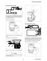
Screw the flange mod. 969-9109 on the pump,
taking care of the o-ring right position.
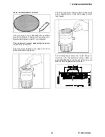
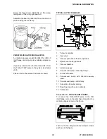
TYPICAL LAYOUT DIAGRAM
Assemble the seal ring and lock the vent device in
position using the KF klamp.
1. Turbo-V
controller
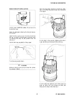
VIBRATION ISOLATOR INSTALLATION
2. Vent
valve
A vibration damper model 969-9340 for ISO 63
inlet flange version pump is available as accesso-
ries.
3. Vacuum pump shut-off valve (optional)
4. System vent valve (optional)
5. Vacuum
chamber
It typically reduces the vibration transmitted from
the Turbo-V 70LP pump to the system by a factor
of 20.
6. Ionization
gauge
7. Fore-vacuum pump connecting flange
8. Oil mist eliminator
Please refer to the relevant instruction manual.
9. Fore-vacuum pump with internal one-way
valve
10. Fore-vacuum pump control relay
11. Connection for water cooling
12. Roughing line with valve (optional)
13. Turbopump
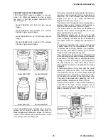
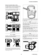
Connection A - HIGH VACUUM FLANGE
To connect the Turbo-V70LP pump to the ISO
inlet flange, remove the outer ring and position the
centering ring as shown in the figure.
Then fix the two flanges with the clamps or claws
as shown in the figure.
34
87-900-862-01(E)


