background image

Varian

, Inc.


2700 Mitchell Drive 
Walnut Creek, CA 94598-1675/usa


Saturn


2000 GC/MS

 Hardware Manual


©Varian, Inc. 2002

-2003

 Printed in U.S.A.


03-914

978

-00:Rev. 

1


Содержание Saturn 2000 GC/MS

Страница 1: ...Varian Inc 2700 Mitchell Drive Walnut Creek CA 94598 1675 usa Saturn 2000 GC MS Hardware Manual Varian Inc 2002 2003 Printed in U S A 03 914978 00 Rev 1...

Страница 2: ...lly reproduced distributed or printed in its entirety provided this copyright and statement are attached Any modification or any other reproduction distribution or use of this document or portions her...

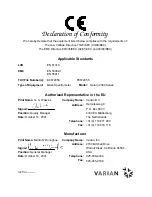
Страница 3: ...odel Saturn 2000 Series Authorized Representative in the EU Print Name G A Wassink Signed Position Quality Manager Date October 16 2001 Company Name Address Varian B V Herculesweg 8 P O Box 8033 4330...

Страница 4: ...we live up to a standard of quality that you can count on today and into the future Our Quality System has received ISO 9001 certification number FM21797 The quality systems that earned us ISO 9001 r...

Страница 5: ...Qualit tsstandard bieten auf den Sie heute und in Zukunft rechnen k n nen Unser Qualit tssystem hat die ISO 9001 Zertifikatnummer FM21797 erhalten Die Qualit tssysteme der ISO 9001 Registrierung haben...

Страница 6: ...garantir et de maintenir un niveau de qualit Lesdites proc dures ont re u l homologation ISO 9001 num ro FM21797 Les syst mes de qualit qui ont re u l homologation ISO 9001 pr sentent des avantages di...

Страница 7: ...quale il cliente pu contare oggi come nel futuro Il nostro Sistema di Qualit ha ottenuto la certificazione ISO 9001 col numero FM21797 I sistemi di qualit per i quali abbiamo ottenuto l omologazione I...

Страница 8: ...ificaci n ISO 9001 representan beneficios directos para nuestros clientes haremos llegar nuestros aparatos m s r pidamente que nunca Podemos cumplir con pedidos urgentes a n m s deprisa Atenderemos su...

Страница 9: ...e instrument or accessory Repair or replacement under warranty does not extend the original warranty period Repair or replacement under warranty claims shall be made in Varian s sole discretion either...

Страница 10: ...die urspr ngliche Garantiezeit Reparatur oder Austausch unter Garantieanspr chen soll in Varian s ausschlie lichem Ermessen entweder durch einen Serviceingenieur beim Kunden oder durch Erm chtigung de...

Страница 11: ...es d un recours est laiss l enti re discr tion de Varian soit par l envoi d un technicien de maintenance sur le site du client soit en autorisant le client retourner l accessoire ou l instrument d fec...

Страница 12: ...razioni o le sostituzioni in garanzia verranno effettuate ad esclusiva discrezione della Varian inviando sul posto un tecnico o autorizzando la resa dello strumento o dell accessorio difettoso alla Va...

Страница 13: ...prolongan el per odo de garant a original Las reparaciones o sustituciones en per odo de garant a se efectuar n a criterio exclusivo de Varian enviando un representante de servicio posventa a la inst...

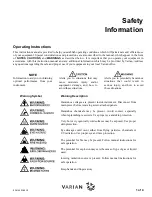
Страница 14: ...oderate injury and or equipment damage and how to avoid these situations Alerts you to potentially hazardous situations that could result in serious injury and how to avoid these situations Warning Sy...

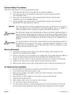
Страница 15: ...used for the analysis of hazardous biological radioactive or toxic samples prior to any instrument service being performed or when an instrument is being returned to the Service Center for repair Ele...

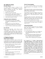
Страница 16: ...sh Chromatography The operator should be familiar with the physico chemical properties of the components of the mobile phase Keep solvents from direct contact with the polyurethane supply tubing as ce...

Страница 17: ...chnical support and training can be provided by qualified personnel on both a contractual or as needed basis Varian Analytical Instruments Sales Offices For Sales or Service assistance and to order Pa...

Страница 18: ...uf die Vermeidung dieser Situationen hin Warnungssymbol Warnungsbeschreibung WARNUNG ELEKTRISCHER SCHLAG Gef hrliche Spannungen bestehen innerhalb des Instruments Trennen Sie das Ger t vom Netz bevor...

Страница 19: ...t f r Analysen gef hrlicher biologischer radioaktiver oder toxischer Proben benutzt worden ist Elektrische Gefahren L sen Sie das Instrument von allen Stromquellen bevor Sie Schutzpaneele entfernen da...

Страница 20: ...durchf hren ffnen Sie niemals eine unter Druck stehende L sungsmittelleitung oder ein Ventil Halten Sie zuerst die Pumpe an und lassen Sie den Druck auf Null abfallen Benutzen Sie splittersichere Res...

Страница 21: ...zung und Training bieten wir Ihnen durch qualifizierte Chemiker sowohl auf einer Kontraktbasis als auch nach Ihren Erfordernissen an Varian Analytical Instruments Verkaufsb ros F r Verkaufs oder Servi...

Страница 22: ...mment rem dier cette situation Symboles d avertissement Description ATTENTION RISQUE D ELECTROCUTION Exposition des tensions dangereuses D brancher le mat riel du secteur avant de d visser les panneau...

Страница 23: ...giques dangereux radioactifs ou toxiques avant que n en soit effectu la maintenance Risques de chocs lectriques D connecter le mat riel de toute source d alimentation avant d en d monter les panneaux...

Страница 24: ...p rations de maintenance de routine Ne jamais d connecter un conduit de solvant ou une vanne sous pression Arr ter pr alablement la pompe et laisser la pression descendre z ro Utiliser des r servoirs...

Страница 25: ...el sp cifique support technique et service de formation assur s par des chimistes qualifi s sur base contractuelle ou en fonction des besoins sp cifiques Points de vente des instruments analytiques Va...

Страница 26: ...ZIONE Descrizione del Pericolo ATTENZIONE Pericolo di folgorazioni Nello strumento sono presenti tensioni pericolose Scollegare il cavo di alimentazione prima di togliere il pannello fissato con le vi...

Страница 27: ...zzato per l analisi di campioni biologicamente pericolosi radioattivi o tossici Pericoli Elettrici Prima di togliere i pannelli di protezione scollegare lo strumento da tutte le alimentazioni elettric...

Страница 28: ...routinaria del sistema Non smontare mai una linea del solvente od una valvola quando il sistema sotto pressione Fermare prima la pompa ed aspettare che la pressione scenda a zero Usare dei contenitor...

Страница 29: ...a piu il costo delle parti A richiesta si possono avere corsi per operatori sia sotto forma di contratto che a tariffe da concordare Uffici Vendite della Divisione Strumenti Analitici della Varian Per...

Страница 30: ...grosas que pueden causar serios da os y c mo evitar esas situaciones S mbolo Descripci n ATENCI N PELIGRO DE DESCARGA EL CTRICA El instrumento utiliza voltages peligrosos Desconecte el interruptor gen...

Страница 31: ...stras peligrosas de origen biol gico radioactivo t xico antes de comenzar a realizar cualquier an lisis Peligros El ctricos Desconecte el instrumento de todos las conexiones el ctricas a la red antes...

Страница 32: ...e rutina Nunca abra una l nea una v lvula bajo presi n Apague la bomba antes y deje que la presi n baje a cero Utilice dep sitos irrompibles que sean capaces de operar a 50 60 psi Mantenga cerrada la...

Страница 33: ...a y materiales El mantenimiento y el entrenamiento se realiza por ingenieros cualificados bajo Contrato petici n Oficinas de Instrumentaci n Anal tica Varian Para cualquier consulta sobre Instrumentac...

Страница 34: ...d Turbomolecular Pump Controller 27 Main Power Circuit 27 Power Board 28 The RF Generator Assembly 29 The Manifold Electronics Assembly 30 The Data System 32 Computer Instrument Interface 32 The Compu...

Страница 35: ...Changing a Channel from Liquid to Gas Operation 70 Changing a Channel from Gas to Liquid Operation 72 Leak Checking 73 Cross Contamination Effects 73 Hints for Successful Operation of the MCI Module...

Страница 36: ...jector Maintenance 119 1079 Injector 120 Remove the Glass Insert 121 Replace the Glass Insert 122 Clean the Glass Insert 123 Deactivate the Glass Insert 124 How to Remove the Capillary Column from the...

Страница 37: ...aphic Problems 146 Correction of Solvent Tailing or Broadening Problems 147 Correction of Tailing Sample Peaks for Particularly Active Components 147 Correction of Low Response and Severe Tailing with...

Страница 38: ...Components 162 Pump Spares Pumps Pump Conversion Parts 162 Diffusion Pump Spares 163 GC Spares 164 Tools Test Samples etc 164 Additional Saturn Spares 165 CI Parts Spares 165 Multiple CI Module Parts...

Страница 39: ...2000 MS Hardware Maintenance 6 Contents...

Страница 40: ...ge 2 Samples are injected either manually or via the AutoSampler onto the capillary column through the GC injection port The gas chromatograph then separates the sample molecules Effluent from the GC...

Страница 41: ...000 MS Hardware Maintenance 8 Functional Description A Foreline Pump B Transfer Line C GC Oven D Capillary Column E Turbomolecular Pump F Ion Trap Assembly Principal Components of Saturn GC MS Top Vie...

Страница 42: ...ed Fourplexes each rated at 115 Vac 15 60 Hz 20A or 230 Vac 15 50 Hz 10 16 A GASES Carrier Gas Ultra high purity helium purity 99 998 with less than one ppm each of water oxygen and total hydrocarbons...

Страница 43: ...er line Vacuum manifold including the ion trap Vacuum pump and controller RF coil and generator Pneumatics manifold Mechanical Assemblies The Saturn mechanical assemblies include the following Control...

Страница 44: ...Valve I Cal Gas Adjust Saturn 2000 GC MS Mass Spectrometer Cooling Fans To prevent overheating do not block air intakes Turbomolecular Pump System Two fans mounted on the rear of the spectrometer cool...

Страница 45: ...air is drawn over the manifold electronics ducted over the Peltier baffle s heat sink and expelled through the rear of the instrument The diffusion pump controller monitors operation of this fan Fan f...

Страница 46: ...System The turbomolecular vacuum system evacuates excess water vapor air and carrier gas from the mass spectrometer ion trap assembly Principal turbomolecular vacuum system components include Vacuum...

Страница 47: ...zer flange Four additional inlets introduce material into the vacuum manifold These inlets include One for the transfer line One for the CI reagent gas One for introduction of the calibration gas One...

Страница 48: ...air leak in the system or that the pump is too warm If this is the case you will have to locate and fix the leak to make your system fully operational Diffusion Pump Vacuum System The diffusion pump...

Страница 49: ...hown A Manifold B Peltier Baffle C Diffusion Pump D Inlet Seal E Inlet Clamp F Analyzer Assembly G Pneumatics Manifold H RF Coil Cross Section of the Diffusion Pump Vacuum System Peltier Baffle The Pe...

Страница 50: ...hed the diffusion pump s required operational pressure after fifteen minutes the controller will provide power to the diffusion pump After another fifteen minutes thirty minutes total the diffusion pu...

Страница 51: ...gas vial and vent valve The vent valve is a manually operated valve that connects to atmosphere via the pneumatics manifold You open and close the vent valve via a toggle arm which is accessible from...

Страница 52: ...tes to the GC prevents hot air leakage from the GC Oven Transfer Line A Spring B Boot C Tie Wrap D Washer E Transfer Line Tip F O Ring G Heat Exchanger H Nose I E Ring J Ferrule K Nut A bayonet mount...

Страница 53: ...ngue G Nose Hole N Analyzer Assembly Lock Down Tabs Transfer Line Exploded View Ion Trap Assembly The ion trap assembly consists of Trap oven Filament assembly Electron gate Ion trap electrodes 3 Quar...

Страница 54: ...nerates the heat A thermal well measures the oven temperature In addition the oven holds the ionization filaments and acts as a lens for focusing the ionizing electrons before they enter the trap Fila...

Страница 55: ...1 but it may be as high as 5 1 Electron Gate The electron gate is a cylindrical electrode that controls the entry of electrons into the ion trap cavity When electrons emitted from the heated filament...

Страница 56: ...imensional hyperbolic electric field This field is capable of trapping the ions in stable aperiodic orbits As the RF voltage increases however the ion trajectories become unstable in increasing order...

Страница 57: ...again strike the inner surface of the multiplier resulting in the emission of more electrons This configuration produces a cascade of electrons that are accelerated toward ground potential at the exi...

Страница 58: ...first is reducing the vacuum system pressure to a level that will allow the operation of high vacuum pumps such as turbomolecular pumps and diffusion pumps The second is maintaining the vacuum system...

Страница 59: ...ds reside in an electronics enclosure that is separated from the analyzer section by a sheet metal bulkhead The manifold electronics are enclosed directly above the analyzer The RF generator attaches...

Страница 60: ...ches Main Power Circuit Line power of 115 Vac 15 60 Hz 3 Hz or 230 15 Vac 50 Hz 3 Hz first enters the rear panel of the mass spectrometer through J1 then passes through the line filter and the circuit...

Страница 61: ...n the power board and the manifold electronics assembly The 20V and 20V dc power supplies which supply the voltages to the SAP Wave and RF generator board s analog circuitry The 24 Vdc power supply su...

Страница 62: ...ielded housing beneath the vacuum manifold encloses the coil and RF detector circuit board The RF generator circuit board is attached to the back of the shielded housing The RF generator circuit board...

Страница 63: ...ies high voltage 800 to 3000 Vdc to the cathode of the electron multiplier The integrator circuit which receives the amplified ion current from the anode of the electron multiplier converts the curren...

Страница 64: ...he SAP Wave board is accessed through two connectors on the rear panel of the instrument J42 is an IEEE connection used for interconnection to the Data System J43 is a D shell connector labeled Remote...

Страница 65: ...disk drive includes programs to control the Saturn GC MS to automatically set Saturn system parameters and to oversee scan control data acquisition and data processing programs For a complete descrip...

Страница 66: ...or MCI Module The installation and operation of these options is described later in this section Installing CI Reagent Gas Before evacuation new gas lines will contain a significant amount of adsorbe...

Страница 67: ...nlet pressure of 15 psi 1 bar Isobutane Isobutane should have a purity of 99 99 or better Use a gas cylinder with a two stage pressure regulator that has a stainless steel diaphragm and maximum inlet...

Страница 68: ...r Vacuum Pump or Diffusion Pump Vacuum System 3 Verify that the CI gas solenoid valves are closed When these valves are closed the CI Gas icon to the left of the ion trap symbol is not green If the CI...

Страница 69: ...ut of until it is firmly seated Be careful not to scratch the tube Tighten the two screws 10 Ensure that the secondary valve on the regulator on the gas cylinder is closed 11 Open the main control val...

Страница 70: ...as line In this case the MS system probably has an air leak You will need to fix the leak as described in the Troubleshooting Section Be sure to check for leaks around The CI GAS port on the rear of t...

Страница 71: ...2000 Maximum Reaction Time sec 60 60 60 Prescan Ion Time sec 100 100 100 If you have installed the Liquid CI Inlet or the Multiple CI Module the following parameters may be used for standard liquid C...

Страница 72: ...ions should reach a minimum at less than half the height of the m z 41 ion The m z 54 ion CH3CHCNH will be present at 10 15 the height of m z 42 Too much acetonitrile in the trap can cause early filam...

Страница 73: ...uid CI Inlet Option You may review the installation and use of the Liquid CI Inlet on the Saturn 2000 Maintenance Tutorial CD Alternatively you may read the instructions that follow in this section In...

Страница 74: ...0026 01 B Viton O ring 03 930109 07 F Restrictor 03 930024 01 C O ring Retainer 03 930025 01 G L Bracket 03 930027 01 D Reservoir Bulb same as Cal Gas Chamber 03 920270 00 H Viton O Ring 03 930109 04...

Страница 75: ...he CI shut off block and tighten the 2 screws from the rear of the instrument 4 Replace the front restrictor a Remove the existing short gas restrictor 03 930596 01 from the bottom of the pneumatics m...

Страница 76: ...he CI valves Do not turn on the filament or multiplier for about 2 3 minutes after opening the CI valves from the Instrument Page A convenient way to verify that air and water have been removed suffic...

Страница 77: ...e to increase or decrease the amount of reagent entering the trap until the resolution between M and M 1 just starts to degrade For best results when using acetonitrile use a filament emission current...

Страница 78: ...the Saturn MS on the right of the diagram These valves are always controlled together both ON or both OFF The control of the Valve States is from the External Events Valve States section of the GC The...

Страница 79: ...klist 1 Preparing the Mass Spec a The Saturn MS should be shut down vented and unplugged 2 Tools Required a 2 Philips screw driver b Small tipped straight screw driver c 5 32 in or 4 mm drill bit d El...

Страница 80: ...trip 9 Position the register plate 0 25 inches 0 6 cm from the open front door and 5 25 inches 13 3 cm from the bottom Be sure to position the plate parallel to the open front door Press firmly to adh...

Страница 81: ...spec 15 Guide the two tubes past the power board and through the opening in the chassis halfway up the middle bulkhead behind the front panel Leave the tubes protruding out the opening for the mass sp...

Страница 82: ...haped tube to the two right openings in the pneumatics block 23 Tighten the four screws on top of the pneumatics block Do not over tighten them 24 Cut the Tygon tubing which is running from the pneuma...

Страница 83: ...to Edit the Valves 9 The cursor should be on Valve type number 1 Press the DECR key until Event A is displayed Press the down arrow cursor key 10 The cursor should be on Valve type number 2 Press the...

Страница 84: ...CI Module Cable Connections to the GC External Events Board A cable to the External Events board of the GC connects each Channel of the MCI Module Upon installation of the MCI Module make these connec...

Страница 85: ...er eye and skin protection 5 Use the 5 mL syringe supplied in the Accessory Kit to fill the bulb halfway with 3 mL of the chosen CI reagent liquid 6 Carefully reinsert the bulb in the inch inlet port...

Страница 86: ...r Each CI Reagent to adjust CI reagent flows Selecting Reagent Channels from the 3800 GC Keyboard To program reagent Channels from the GC keyboard select the External Event or Valve for the chosen Cha...

Страница 87: ...400 or 3600 GC Control You will see the following screen If you wish to adjust flows of all three CI reagents in the MCI Module you will want to save three Methods with Relays turned on for each speci...

Страница 88: ...l of the MCI Module to be selected for adjustments the GC MS method should have the correct Channel selected in the GC Sample Delivery section of the Method Using the Star Toolbar or the Start Program...

Страница 89: ...ill now show all three External Events with the correct Valve position but all Valve States are off In Row 2 under Valve 1 double click on the Off symbol or use the arrow key on the right side of the...

Страница 90: ...method to create a single segment method for CI Auto acquisition You may later use this method as a default method for CI acquisition with the MCI Module so you may wish to adjust method parameters s...

Страница 91: ...he menu command File Save As ChannelA mth Modify this method for the CI reagents in Channels B and C and save the new methods with the menu command File Save As ChannelB mth or ChannelC mth You may th...

Страница 92: ...can Range are displayed 5 Click on the Adjustments tab dialog and then choose Acetonitrile as the gas and click on Adjust 6 The adjustment process will begin as shown 7 If after a couple of minutes th...

Страница 93: ...e requires a unique GC MS method The GC section of the method MUST contain External Events programming to select the CI reagent in Channel A B or C The MS section of the method MUST have CI mode selec...

Страница 94: ...oven program The following program requires a 30 minute run Choose the Method Directory item Sample Delivery and create a Sample Delivery method with all External Events Off Click on the MS Method Edi...

Страница 95: ...Directory item Sample Delivery to turn on the External Event for that CI gas Click on the Add button on the right of the window to add another segment and enter 30 under Time so that External Event A...

Страница 96: ...or Default Parameters for Gaseous CI Reagents for suggested background masses Low mass for acquisition should never be lower than the suggested background mass for a given reagent Also note that the...

Страница 97: ...hoose the option Start Programs Saturn GCMS Workstation Automation File Editor The Automation File Editor Dialog Box will open Click on the option File New SampleList Select the name EI_CI for the new...

Страница 98: ...rther to the right in the SampleList This will allow you to enter the Method and the 8200 AutoSampler Rack Vial positions to use for each sample For this example enter Vial 1 for the first pair of run...

Страница 99: ...method ACN_CI After this has been done the correct GC MS methods are specified for all entries in the SampleList Multiple CI Reagents in Consecutive Runs If unique GC and MS methods for all three rea...

Страница 100: ...run then methanol CI Event B Channel B and methane CI Event C Channel C in the succeeding ten minute segments To develop this method open the Method Builder and choose to edit ACN_CI mth After openin...

Страница 101: ...k the Add twice to create two additional Segments Segment 2 is left as an acetonitrile CI segment ending at 10 minutes Segment 3 parameters are changed in the Ionization Mode tab dialog to those for m...

Страница 102: ...lue less than that of the lowest reagent ion As shown in the chromatogram the ions for soft CI reagents such as isobutane or acetonitrile first show a high level spike and then rapidly equilibrate aft...

Страница 103: ...will be absorbed to some extent in the O rings sealing the vial restrictors and solenoids for each channel Cleaning Reservoir Bulbs Withdraw the solvent from the reservoir with the 5 mL Luer syringe s...

Страница 104: ...ry kit for storage 6 Remove the lower restrictor 03 930596 02 installed in the two 1 8 inch ports underneath the manifold block Save the restrictor in a clean particle free bag to prevent contaminatio...

Страница 105: ...e four screws located between the solenoid valves on top of the module 5 Remove the gas adapter fitting with the long gas line restrictor 28 695138 00 and 03 930597 00 respectively from the inch port...

Страница 106: ...ng the tubing and O ring but usually a new O ring is required Extras are provided with the MCI module and also in the accessory kit Cross Contamination Effects Vapor from liquid CI reagents is absorbe...

Страница 107: ...exhausted 3 The MCI Module may be used in several different ways to acquire data on a sample for qualitative identification Using deuterated reagents can provide extra information when the data are c...

Страница 108: ...hutdown sequence takes at least 30 minutes The Saturn GC MS heaters are turned OFF The GC temperature zones should be cooled downed before maintenance is performed The diffusion pump heater is turned...

Страница 109: ...ar on startup or during operation Turn OFF main power by placing switch at rear of system to OFF down position Manually vent the system for at least 5 minutes using the lever on the front panel CAUTIO...

Страница 110: ...as reached temperature approximately 15 minutes the ion trap electronics can be turned on If a diffusion pump fault occurs the system will go to the shutdown sequence The user may check for faults on...

Страница 111: ...2000 MS Hardware Maintenance 78 System Start up and Shutdown...

Страница 112: ...mputer screen Refer to Pump Maintenance Section The oil level and condition should be checked with the pump switched off but still warm 1 The oil level should be between the maximum and minimum levels...

Страница 113: ...he life of the oil However the pump oil may be rejuvenated with a weekly purge Purging can be done without interrupting system operation However this should not be done while the Saturn is acquiring d...

Страница 114: ...Pump weighs 25 kg 55 lb Use proper lifting techniques 6 Place an oil pan beneath the drain port to catch any spillage Hazardous chemicals may be present Avoid contact with skin Use proper eye and ski...

Страница 115: ...uring this operation 6 Stop the pump drain the flushing oil and replace as described previously Check Cooling Fans Turbomolecular Pump System To prevent overheating do not block air intakes The coolin...

Страница 116: ...Adjust If the fans are excessively noisy i e if they whine or whir one of the fans may be about to fail and it should be replaced To identify which of the two fans is about to fail proceed as follows...

Страница 117: ...he Saturn GC MS cover by grasping both sides and lifting up 5 Remove the lower side panel with a Phillips screwdriver 6 Disconnect the 1 8 in pneumatics exhaust tube from the vacuum hose elbow 7 Disco...

Страница 118: ...urbomolecular cable is tilted towards the bulkhead i e toward the left as viewed from the rear of the instrument Take care not to scratch the sealing surface on the manifold in front of the turbomolec...

Страница 119: ...ice switch are turned ON refer to the figure showing these zones Proceed as follows 1 Zone 1 Upper analyzer compartment The Zone 1 fan is located in the top left of the rear panel as viewed from the f...

Страница 120: ...e pump s fluid level and condition which should be checked monthly The fluid can only be checked by removing the left side cover NOTE If the cover is off for more than five minutes the pump will overh...

Страница 121: ...shutdown tab from System Control and click on shutdown See section on system Start up and Shutdown CAUTION Do not attempt to vent the MS by any other means Venting through the foreline connections or...

Страница 122: ...rom the thermocouple gauge 12 Unscrew the plastic nut and slide it up the 1 8 pneumatics exhaust tube Withdraw the tube from the elbow using a twisting motion 13 At the rear of the instrument loosen t...

Страница 123: ...de cover and fasten in place with the four screws and two spacers 36 Bring the MS alongside the GC and refit the transfer line 37 Reconnect the manifold and trap heater cables 38 Refit the top cover 3...

Страница 124: ...old and trap heater cables 19 Turn the service switch to the ON position 20 Refit the top cover 21 Carefully slide the MS up to the GC 22 Bring up System Control to download the mass spectrometer soft...

Страница 125: ...end faces the diffusion pump and pulling the clamp toward you 8 Lift the elbow up and secure it to the manifold lugs with a rubber band or tie wrap CAUTION Be careful not to scratch or damage sealing...

Страница 126: ...ntroller 17 Remove the pump and set it on its base Topping Off the Diffusion Pump Fluid Level 1 Remove the pump 2 Slowly pour a little diffusion pump fluid 03 930639 01 through one of the holes in the...

Страница 127: ...late Q Ejector Stage I Base Plate Hazardous chemicals may be present Avoid contact with skin Use proper eye and skin protection WARNING Toxic residues from mass spectrometer samples will build up in u...

Страница 128: ...uitable container 12 Clean the interior of the pump body with acetone and rinse with isopropyl alcohol Allow to air dry CAUTION Do not submerge the pump body as the solvents will be absorbed into the...

Страница 129: ...p 2 Turn the pump upside down and drain the fluid into a suitable container Hazardous chemicals may be present Avoid contact with skin Use proper eye and skin protection WARNING Toxic residues from ma...

Страница 130: ...p in the MS ATTENTION IMPORTANT NOTE The new heater will give off an odor during the first thirty minutes of operation The odor results from the baking of the anti seize lubricant and certain compound...

Страница 131: ...r to the left as possible while still allowing room to turn the wing nut 17 Rotate the diffusion pump so the elbow lies as close to the manifold as possible 18 Tighten the wing nut on the exhaust clam...

Страница 132: ...F position 2 Check that all the heater cables are plugged in 3 Check that all the Saturn covers are in place especially the left side cover and the Peltier baffle ducting 4 Plug in the Saturn power ca...

Страница 133: ...aintenance procedures on computer screen Refer to MS Maintenance Section You will need to service the ion trap if it needs to be cleaned or requires replacement of the filaments or multiplier The foll...

Страница 134: ...ansfer Line NOTE Fully vent the analyzer assembly before attempting to retract or remove the transfer line Vacuum makes retraction of the transfer line difficult To retract the transfer line proceed a...

Страница 135: ...ure the transfer line is retracted Otherwise you will not be able to remove the analyzer assembly without damaging the analyzer To remove the analyzer assembly proceed as follows 1 Remove the top cove...

Страница 136: ...out of the way during the procedure and return it to its original position once the analyzer is replaced 6 Tilt the rear end up carefully to remove the analyzer 7 Move the analyzer assembly toward th...

Страница 137: ...3 To protect the electron multiplier place it with one of its sides facing down on a flat surface The glass multiplier grid should not be touching anything To install the new electron multiplier proce...

Страница 138: ...filament entrance hole for carbon deposits Carbon buildup in this area can lead to lower sensitivity and or shorter filament lifetime Area should be cleaned before replacing filament assembly 6 Place...

Страница 139: ...omponents To clean the trap components you will Disassemble the trap components Clean the trap components Reassemble the trap Disassemble the Trap Components 1 Place the oven filament side down on its...

Страница 140: ...coated parts Clean the quartz spacers NOTE For SilChrom coated electrodes Do Not use Aluminum Oxide Clean Stainless Steel Parts To clean the filament endcap RF voltage ring electrode and exit endcap p...

Страница 141: ...Subject the beaker and its contents to ultrasound for about 1 minute NOTE Once the ion trap parts are clean wear clean lint free gloves in subsequent handling of the parts to prevent contamination Do...

Страница 142: ...5 to gently scrub the trap parts The trap is rinsed and then sonicated in water followed by two sonications in methylene chloride or methanol DO NOT use Aluminum Oxide or other abrasives because this...

Страница 143: ...ap oven assembly 9 Visually check the transfer line hole making sure that notches in the quartz spacer and exit endcap electrode are aligned and centered in the trap oven 10 Tighten the screws Re inst...

Страница 144: ...OTE Take care not to scrape or bang the analyzer parts e g the trap oven assembly electron multiplier filament wires etc against the stainless steel manifold flange 2 With a slight forward downward ti...

Страница 145: ...as follows 1 Make sure that the power switch on the back of the mass spectrometer is in the OFF position 2 Check that all heater cables are plugged in 3 Plug in Saturn power cable 4 Turn ON Saturn po...

Страница 146: ...ach of the four retaining screws about 3 turns with a Phillips screwdriver The four screws are located on the top of the pneumatics manifold 2 Pull the cal gas vial down gently with a slight twisting...

Страница 147: ...2000 MS Hardware Maintenance 114 Mass Spectrometer Maintenance...

Страница 148: ...arian service representative For maintenance problems where mechanical or electrical assemblies need to be repaired or replaced please call your local Varian service center There are certain maintenan...

Страница 149: ...n a Gas Chromatograph The following information refers to general leak checking procedures for the 3800 Gas Chromatograph Specific information regarding individual 3800 components will be presented in...

Страница 150: ...plished by adjustment of manual pneumatic controls or Electronic Flow Control For information on setting carrier gas pressure see the Basic Operation section of the 3800 Getting Started manual 6 Shut...

Страница 151: ...ed on the Rear of the GC Gas purifiers supplied by Varian and most other chromatography suppliers are equipped with 1 8 Swagelok fittings This facilitates easy removal and replacement of purifiers In...

Страница 152: ...the replacement filters The following are the stand alone gas purifiers available from Varian Purifier Part Number Indicating oxygen trap CP17970 Indicating moisture trap CP17971 Combined hydrocarbon...

Страница 153: ...l you feel resistance from the septum then tighten an extra 1 4 turn Turn on the carrier gas supply On occasion to save time you may want to change a septum while the injector is hot Use an injector w...

Страница 154: ...00084 00 Injector nut wrench 03 908423 00 Flat blade screwdriver short handle Clean laboratory tissue Graphite ferrules 03 925342 02 Insert ferrule positioning tool 03 925385 00 1079 Injector Cross Se...

Страница 155: ...port nut 6 To remove the graphite ferrule from the glass insert use clean lab tissues to hold the graphite ferrule Item 5 and the glass insert Gently turn the glass insert while you pull off the graph...

Страница 156: ...to the split mode and purging with carrier gas for 30 min at 300 C Clean the Glass Insert Glass inserts must be clean and free from sample residue and particulate matter such as bits of septum rubber...

Страница 157: ...ts only after they have been thoroughly cleaned using the above procedure 4 Sonicate the inserts in the cylinder for 10 min Rinse the inserts 3 times with 10 mL isooctane hexane or toluene Each rinse...

Страница 158: ...rt insert ferrule septum and injector nut 11 To check whether the injector is leak tight connect a flow meter to the split vent Set the Relay to the split mode If the flow meter indicates a flow less...

Страница 159: ...cable 2 Grasp the nose of the transfer line then rotate counterclockwise as you press lightly toward the manifold Gently slide the transfer line away from the manifold 3 Remove the nose clip and then...

Страница 160: ...slightly to break it at the mark The column should break cleanly 9 Using a Kimwipe tissue dipped in methanol carefully wipe the last 15 cm 6 0 in of the column 10 Be sure to wipe toward the end of th...

Страница 161: ...g cable to the mass spectrometer 21 Gently push the mass spectrometer toward the GC until the transfer line boot fits snugly over the collar on the side of the GC oven The capillary column nut should...

Страница 162: ...LTEST mixture This multicomponent mixture is very well suited to troubleshooting injector and column problems Please see How to Run the COLTEST Sample for a description of the use of this test mixture...

Страница 163: ...you must remove the column from the ion trap by shutting down the system and capping the transfer line with a no hole ferrule How to Troubleshoot Problems with Spectra The following describes the comm...

Страница 164: ...ents and select Adjust RF Ramp 3 Adjust the RF ramp by turning the RF tuning screw 4 Adjust the RF ramp until the highest value is minimized Check the Parameter Settings Check whether you have set ina...

Страница 165: ...moving the trap from the electronics assembly there will be continuity to ground 3 Check whether there is a problem with the electron multiplier proceeding as follows a Under Monitor States click on M...

Страница 166: ...de and Default values for other parameters NOTE If after performing these tests you are still unable to isolate the cause of the problem contact your Varian Customer Support Representative What To Do...

Страница 167: ...cause of the problem contact your Varian Customer Support Representative What To Do If the Resolution is Poor But the Air and Water Levels are Acceptable If the peaks are broader than you would have e...

Страница 168: ...re that the axial modulation readback is within 20 of the set point If the axial modulation readback is out of this range it will usually result from improper installation of the trap oven causing a s...

Страница 169: ...e Air leaks may result in reduced sensitivity tuning problems and decreased resolution in addition they may reduce the lifetimes of the capillary column filaments and the electron multiplier Check the...

Страница 170: ...confirm that the turbomolecular pump is operating at 100 speed or diffusion pump is ready If it is not you may be sure there is a major air leak 4 Enter System Control Click on Auto Tune Box Click on...

Страница 171: ...2000 MS Hardware Maintenance 138 Troubleshooting Air water Spectrum from a System with a Very High Water Vapor Background...

Страница 172: ...ght of mass 18 to mass 19 is much less than 10 1 your system contains excess water vapor An Air Water Spectrum Obtained from a System with No Significant Air Leaks and Little Water Vapor as Indicated...

Страница 173: ...ceably greater than that at mass 18 The ratio of the peak height at mass 28 to that at mass 32 is greater than 4 1 The 100 scale counts value has increased to greater than 500 The ratio of the peak he...

Страница 174: ...required for the water vapor to desorb from surfaces in the vacuum system and for the water level to drop to a stable level Never operate your Saturn if the mass 18 and 19 peaks are the same height o...

Страница 175: ...ings Argon diffuses very rapidly from the fitting you are testing toward a true leak This could lead you to mistakenly identify the fitting that you are testing as the leak source Check for leaks Spra...

Страница 176: ...correct a leak at the connections between the capillary column and the injector or transfer line proceed as follows Make sure that you are using ferrules of the correct size i e 0 4 mm for 0 25 mm ID...

Страница 177: ...ce directory of the software Set Up the Injector Conditions If you are using SPI 1079 programmable injection proceed as follows Hold an initial temperature of 40 C for 0 1 min then ramp the temperatur...

Страница 178: ...7 Turn cal gas OFF The COLTEST test mixture contains the following compounds at levels of 1 to 5 ng L No Compound Formula Integer Weight Quantitation Mass 1 decane C10H22 142 57 2 1 octanol C8H18O 130...

Страница 179: ...pound please refer to the SaturnView help or section in the Software Reference manual How to Troubleshoot Common Chromatographic Problems The COLTEST mixture includes polar or active compounds such as...

Страница 180: ...ction For a splitless injection the vent flow should be at least 70 mL min The injector should be switched to the split mode 30 to 90 sec after the injection Correction of Tailing Sample Peaks for Par...

Страница 181: ...henol and 2 ethylhexanoic acid in the COLTEST mixture Lack of Reproducibility of Peak Size Symptom Solution Leaking or partially plugged syringe Visually check that the syringe is pulling up the sampl...

Страница 182: ...g plasticizers present Confirm that this is indeed the case by running a solvent blank with a new syringe Use certified sample vials and keep the samples refrigerated Check contamination table Impuri...

Страница 183: ...2000 MS Hardware Maintenance 150 Troubleshooting...

Страница 184: ...ceeds 5000 mTorr Large Air Leak a Check the GC column is not broken b Check the foreline hose between the diffusion pump and foreline pump for cracks or collapsed sections c Check all the vacuum seals...

Страница 185: ...heck the cable connections d Open filament Gauge must be replaced e Contact Varian Customer Support Representative 5 Diffusion Pump Overheated a Check the pump is plugged into the diffusion pump contr...

Страница 186: ...g is in place e Check the fan f Check to make sure left side cover is in place g Contact Varian Customer Support Representative 4 High background levels low ionization time in the mass spectra may be...

Страница 187: ...eptum or methyl silicone column coating 77 92 115 128 141 168 184 223 233 260 354 446 Diffusion Pump Fluid Diffusion Pump Fluid 149 Plasticizer Phthalates Vacuum seals damaged by high temperature Solv...

Страница 188: ...ning it in operational condition outside of the power and operating environment limits listed below could cause failures of many types The repair of such failures is specifically excluded from the sta...

Страница 189: ...as much as possible The power cable from the GC is approximately 2m 6 ft long and fitted with National Electronics Manufacturers Association NEMA 5 20P power plugs The NEMA 5 20P power plug and corre...

Страница 190: ...se you may overload the fourplex power source The Interconnect Diagram for Saturn is a diagram for the six power cables from Saturn Never use the free outlet on each of the power sources for equipment...

Страница 191: ...bility decreases All electronic components generate heat while operating This heat must be dissipated to the surrounding air if the components are to operate reliably The turbomolecular pump s tempera...

Страница 192: ...ity standards are maintained If you purchase pure gases in contaminated tanks you may end up with a contaminated system requiring costly and time consuming repair Methane Isobutane CI Reagent Gases wi...

Страница 193: ...pump power only 6 Connect the GC serial cable to the COM1 port on the computer if using a 3400 3600 GC 7 Connect the GC ethernet cable to the ethernet port on the computer if using a 3800 GC There sho...

Страница 194: ...S to its new location Be sure the new location satisfies the power and environmental requirements Parts and Supplies Listed below are part numbers and descriptions for the available Saturn Field Servi...

Страница 195: ...Line Ultra Clean 03 930500 01 Trap Oven 03 930524 01 Clamping Plate 03 930535 02 Quartz Spacer Silica Coated 13 122008 00 Nut 11 32 14 998228 00 Belleville Washer Large 03 930539 01 Thermo Well 03 930...

Страница 196: ...ring Peltier Baffle 03 930288 01 PWA Diffusion Pump Controller 27 229907 00 Thermocouple Gauge 03 930640 91 Diffusion Pump AX65 90V 250W Includes 40 cc Fluid 03 930640 92 Diffusion Pump AX65 165V 250...

Страница 197: ...ID Unpacked Single Gooseneck Insert 5 pk 03 926119 37 1177 4 mm ID Wool Plug Open Insert 5 pk 03 926119 25 1177 4 mm ID Unpacked Open Glass Insert 5 pk 03 926119 38 1177 2 mm ID Wool Plug Open Glass I...

Страница 198: ...CI 03 930101 01 Needle Valve CI Gas 03 930022 91 Liquid CI Inlet Kit 03 930 106 01 CI Solenoid 2 way Chemrez Multiple CI Module Parts Lists Part Number Description 03 930061 01 Manifold Multi CI Inle...

Страница 199: ...lacement O rings for 1 8 inch ports 03 930109 17 O ring 2 108 Buna N Replacement O rings for inch ports 28 694638 00 Ferrule Teflon rear Replacement ferrules for gas adapter 28 694639 00 Ferrule Teflo...

Страница 200: ...are using Cryogenics Information about your GC column i e the manufacturer bonded phase film thickness and ID and length If you are having problems with your computer and or software please be prepare...

Отзывы: