BDR-595D Adela
19
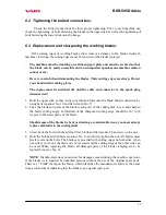
Never put the engine on the side. Oil might get into the exhaust or into the air
cleaner. Best engine placing is with the lower flange dwelling on two lintels which
are at least 7 cm high.
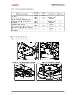
c) Dismount the upper casing and handrail (flat wrenches No. 8, 10, 13). Dismount the
column in front of the driven belt pulley (see Fig. 5.3) (spanner No. 10). Take the old V-
belt off and replace it with a new one. Original V-belt marking is
OPTIBELT
X13x1300Ld 6T6K
(Ld=calculated length). It is also possible to use an equivalent V-belt
made by other manufacturers at a size of
A13x1270 Li
(Li=internal length) or
½“ x
52“La
(La=external length). However, the belt must be made without rubber on sides!
Only such a belt model will guarantee that the blade drive start is smooth at engaging the
clutch.
Should another than the above mentioned original spare belt be used, the machine
manufacturer does not answer for correct and full functioning of the drive!
d) Put the engine back in place. Pins in the driving belt pulley, installed on the engine, must
fall into holes in the rubber element on the driven part of the clutch. Bolt the engine with
three safety nuts with flat washers. Screw the accelerator lever back onto the handlebars.
e) Put the V-belt into the groove in the belt pulley on the engine.
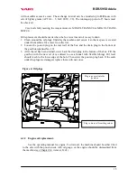
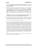
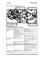
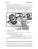
f) Check the operation of the tightening pulley and adjustment of guide lamination. With
the lever on the right handlebar grip fully pressed down, the pulley must ensure a
sufficient belt tension (spring on the cable being extended by about 10 mm as compared
with loose condition). Possible corrections are to be made by means of adjustment bolt
No. 2 (see Fig. 8). With the lever switched off, the pulley must be tilted away from the
longitudinal machine axis at an angle of max. 0 - 5° = with the belt convex side being
approx. 1.5 – 2.0 cm from the bottom of the tightening pulley (see Fig. 7). The cable in
the Bowden of the tension pulley must exhibit no slackness. In the case that the
adjustment bolt is completely screwed out and it is necessary to tighten the V-belt, the
spring on the cable can be hooked into the front hole on the arm of the tightening pulley
(see Fig. 7 bottom, note: this connection can be used already from the manufacturer) and
belt tension can be adjusted once again. Guide lamination on the right side of the machine
must be parallel to the belt and at a maximum distance of 1 – 2 mm from the belt convex
side.
g) Mount the column back to its original position in front of the driven belt pulley, mount
back the upper plastic casing and the handrail.
Содержание BDR-595 D Adela
Страница 1: ...Brush cutter BDR 595 D Adela Instructions for use...
Страница 7: ...BDR 595D Adela 7 LwA 2 1 8 3 4 5 6 7 11 12 9 10...
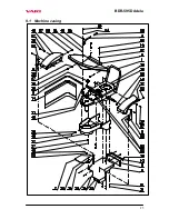
Страница 25: ...BDR 595D Adela 25 9 1 Machine casing...
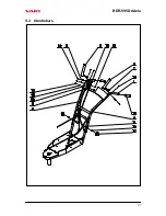
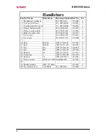
Страница 27: ...BDR 595D Adela 27 9 2 Handlebars...
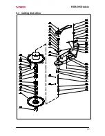
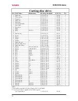
Страница 29: ...BDR 595D Adela 29 9 3 Cutting disk drive...
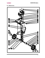
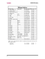
Страница 31: ...BDR 595D Adela 31 9 4 Wheel drive...
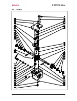
Страница 33: ...BDR 595D Adela 33 9 5 Gearbox...


