background image

Wireless Field Transceiver

Varec, Inc.

29

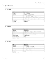
8 Specifications

8.1

General

8.2

Transmit

8.3

Receive

Item

Specification

Data Port

RS-232 and RS-485

Dimensions

See Figure 2-1 on page 7 for details

Power 

• 110/120 VAC (AC Version)
• 30 - 65 VAC and 6 - 90 VDC (Low Voltage Version)

Antenna

• N-type female connector (External antenna required)
• SMA  connector

FCC Identifier

KNY-42182112519

IC Identifier

2329B-FGR2

Table 8-1:

General

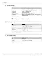
Item

Specification

Frequency

902 to 928 MHz

Output Power

10 mW to 1 W (+30 dBm). See RF transmit power settings.

Range

60 miles Line of Sight, 0 db antenna gain

Modulation

Spread spectrum GSK, 120 or 170 Kbps

Spreading method

Frequency hopping

Occupied bandwidth

230 kHz

Table 8-2:

Transmit

Item

Specification

Frequency

902 to 928 MHz

Sensitivity

• -110 dBm at 10-4 bit error rate
• -108 dBm at 10-6 bit error rate

Selectivity

• 20 dB at f

c

 ± 115 kHz

• 60 dB at f

c

 ± 145 kHz

System gain

140 dB

Table 8-3:

Receive

Содержание RS-232

Страница 1: ...olutions for oil gas defense and aviation applications Installation and Operations Manual Dispatch and Fuels Accounting 8410 Wireless Field Transceiver Transmitter and receiver for wireless RS 232 and...

Страница 2: ......

Страница 3: ...rmission of the Publisher Varec Inc 5834 Peachtree Corners East Norcross Atlanta Georgia 30092 Phone 770 447 9202 Fax 770 662 8939 Trademarks Acknowledged Varec Inc recognizes all other trademarks Tra...

Страница 4: ...warranty clause In no case shall the Seller s liability exceed that stated as Limitations of Remedy in the contract between the Seller and Buyer Use of parts that are not manufactured or supplied by...

Страница 5: ...and safety guidelines presented in this manual when using this product If the user does not follow these instructions properly Varec cannot guarantee the safety of the system Note Comply with all appl...

Страница 6: ...comply with the limits for a Class B digital device pursuant to part 15 of the FCC Rules These limits are designed to provide reasonable protection against harmful interference in a residential instal...

Страница 7: ...dy 10 2 5 3 Selecting an antenna 10 2 5 4 Configuring radios 11 2 5 5 Installing cables and antennas properly 11 2 5 6 Surge protection 11 3 Mounting 13 3 1 Installation Safety Guidelines 13 4 Wiring...

Страница 8: ...ations Manual 7 Factory Default Settings 27 8 Specifications 29 8 1 General 29 8 2 Transmit 29 8 3 Receive 30 8 4 Data Transmission 30 8 5 Power Requirements 31 8 6 Operating Environment 31 9 Ordering...

Страница 9: ...cations between the field instrument and the 8420 Wireless Base Transceiver WBT which is located in the control room Both units are able to provide simultaneous slave repeater functionality The 8410 W...

Страница 10: ...r master or slave may be added In a point to multipoint system the transceiver desig nated as a master is able to communicate with numerous slaves In its simplest form a tank gauge multipoint network...

Страница 11: ...a B Antenna Feed Thru C Electronics Assembly D O Ring E Housing All standard electronics for the 8410 WFT are contained on the circuit board C This includes power field communications a 3 wire tempera...

Страница 12: ...hows how a link might be set up using a repeater The repeater may be sitting on a hilltop or other elevated structure to link the master to the slave In this setup it may be desirable to use an extern...

Страница 13: ...om the master is broadcasted to all three slaves one of which receives it through a multipoint repeater The data is in turn sent out of the RS 232 or RS 485 port of each of the three slaves Figure 1 6...

Страница 14: ...rk is used in applications where data is collected from many instruments and reported back to one central site As such the architecture of such a system is different from point to point applications T...

Страница 15: ...conduit and cabling Refer to Figure 2 1 for housing dimensions Figure 2 1 8410 Wireless Field Transceiver Dimensions 3 To have the correct field connections at the field device ready to connect to the...

Страница 16: ...the user should check with the local safety authorities Always observe equipment labels and warning signs posted in the area 2 3 Unpacking Varec 8410 Wireless Field Transceivers are shipped fully asse...

Страница 17: ...allation Overview To install the transceiver follow the pre site preparation steps shown in the following flowchart Figure 2 2 8410 WFT Installation Sequence Site Identification Site Study Configure R...

Страница 18: ...ore noise and interference from other RF signals in the area A high antenna or cables are more susceptible to damage from lightning strikes 2 5 2 Completing a site study To complete a site study do th...

Страница 19: ...al for more information Verify that there is a proper communications link to the master 2 5 5 Installing cables and antennas properly To properly install cables and antennas ensure that There are no m...

Страница 20: ...Preparing for Installation 12 Installation and Operations Manual...

Страница 21: ...of tank gauging equipment Caution should be exercised when entering any area that is posted or otherwise assumed to contain hazardous gases Always follow OSHA guidelines Obtain a hot permit before re...

Страница 22: ...Mounting 14 Installation and Operations Manual...

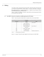
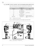
Страница 23: ...page 19 describe the connector assignments for the AC and DC versions of the 8410 WFT 4 1 8410 WFT Connectors Switches and Wiring Diagram AC Version Table 4 1 lists the connectors and switches for wir...

Страница 24: ...Manual Figure 4 1 8410 WFT Wiring AC Version SW1 RS232 RS485 Switch J8 RS232 RS485 In J4 AC Power In J6 RTD In J5 RTD Out AC Voltage Selector SW2 485 SW3 Radio Setup Mode Button J9 24VDC Out 232 Anten...

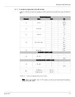
Страница 25: ...Make sure that SW2 the 110 220 switch is in the correct position before applying power to the 8410 WFT Terminal Assignments Connector Name Pin Pin J4 AC IN 1 Line 2 Neutral 3 Earth J5 RTD OUT 1 A 2 B...

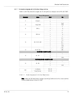
Страница 26: ...otes J1 Voltage In 30 65 VAC 6 90 VDC J5 RTD Feedthrough IN J6 RTD Feedthrough OUT J8 Serial Communications RS 232 RS 485 J9 24VDC OUT SW1 RS 232 RS 485 Switch SW3 Radio Setup Button Puts radio in set...

Страница 27: ...that the AC DC and high low voltage switches are in the correct position before applying power to the 8410 WFT Terminal Assignments Connector Name Pin Pin J1 Voltage In 1 2 J2 Surge GND 1 Earth 2 Ear...

Страница 28: ...Wiring 20 Installation and Operations Manual...

Страница 29: ...ansceiver Using Tool Suite Depending on the radio type a radio may be configured via EZ Config HyperTerminal or FreeWave Tool Suite The following link will allow the user to gain access to the FreeWav...

Страница 30: ...Setting Up the Transceiver Using Tool Suite 22 Installation and Operations Manual...

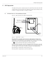
Страница 31: ...prevent false data indications the data lines are typically held in a non asserted state using a small bias current This bias current is normally provided at the host but can be provided at the 8410 W...

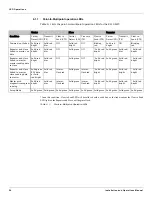
Страница 32: ...king red Repeater and slave linked to master no data Solid red bright Solid red dim Off Solid green Off Solid red bright Solid green Solid red dim Solid red bright Repeater and slave linked to master...

Страница 33: ...flash red Interm flash red Solid green Interm flash red Interm flash red n a n a n a Master calling slave through repeater Solid red bright Solid red dim Solid red bright Solid red bright Off Blinkin...

Страница 34: ...LED Operations 26 Installation and Operations Manual...

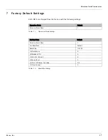
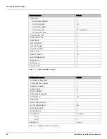
Страница 35: ...lowing settings Table 7 1 Operation Mode Setting Table 7 2 Baud Rate Setting Operation Mode Default Point to Point Slave 1 Set Baud Rate Default Point to Point Slave 1 Set Baud Rate Default Baud Rate...

Страница 36: ...IZE 8 2 MIN PACKET SIZE 9 3 XMT RATE 1 4 RF DATA RATE 3 5 RF XMT POWER 10 6 SLAVE SECURITY 0 7 RTS TO CTS 0 8 RETRY TIMEOUT 255 9 LOW POWER MODE 0 A High Noise 0 B MCU Speed 0 C Remote LED 0 Multipoin...

Страница 37: ...KNY 42182112519 IC Identifier 2329B FGR2 Table 8 1 General Item Specification Frequency 902 to 928 MHz Output Power 10 mW to 1 W 30 dBm See RF transmit power settings Range 60 miles Line of Sight 0 db...

Страница 38: ...n dynamic key Max Link throughput Kbaud standard speed 38 4 Kbaud low speed Data interface RS 232 RS 485 1200 Baud to 230 4k Baud async full duplex TTL RF board level only Table 8 4 Data Transmission...

Страница 39: ...3dB Gain 23 N Female O5 Maxrad Omni 5dB Gain 48 N Male O7 Maxrad Omni 7dB Gain 96 N Male Note Yagi antennas provide increased RF range in one direction Omni Directional antennas provide 360 degree co...

Страница 40: ...Ordering Information 34 Installation and Operations Manual...

Страница 41: ......

Страница 42: ...939 www varec com 2006 Varec Inc All Rights Reserved This document is for information purposes only Varec Inc makes no warranties express or implied in this summary The names of actual companies and p...

Отзывы: