Wireless Field Transceiver
Varec, Inc.
23
6 LED Operations
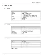
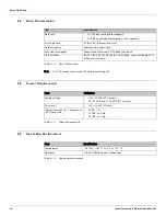
This chapter lists the point-to-multipoint and point-to-point LED operations for the 8410 WFT.
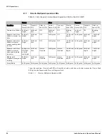
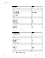
The LEDs located on the radio module provide diagnostic and communication information. Refer
to Table 6-1 on page 24 and Table 6-2 on page 25 for details.
6.1
LED Operations on a Point-to-Multipoint System
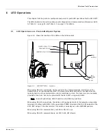
Figure 6-1 shows the location of the LEDs on the radio module.
Figure 6-1: 8410 WFT LEDs — Location
When using RS-485 connectivity, during periods of no communications, all devices on the
network are in a high-impedance state. To prevent false data indications, the data lines are
typically held in a non-asserted state using a small bias current. This bias current is normally
provided at the host, but can be provided at the 8410 WFT using switch SW2.
Note In most applications, SW2 should be set to BIAS (up) position.
When using RS-485 connectivity, the devices at the physical ends of the network are typically
terminated. Setting switch SW3 in the up position (TERM), terminates the RS-485 network at the
8410 WFT using a 100 ohm resistor. This switch is normally set in the UNTERM position.
When using RS-232 communication, set SW1 to RS-232 (up).
When using RS-485 communications, set SW1 to RS-485 (down).
LED's
CARRIER DETECT (CD) LED
TRANSMIT (TX) LED
CLEAR TO SEND (CTS) LED
SW3
SW2
SW1
TERM
UNTERM
BIAS
UNBIAS
RS-232
RS-485
Содержание RS-232
Страница 2: ......
Страница 20: ...Preparing for Installation 12 Installation and Operations Manual...
Страница 22: ...Mounting 14 Installation and Operations Manual...
Страница 28: ...Wiring 20 Installation and Operations Manual...
Страница 30: ...Setting Up the Transceiver Using Tool Suite 22 Installation and Operations Manual...
Страница 34: ...LED Operations 26 Installation and Operations Manual...
Страница 40: ...Ordering Information 34 Installation and Operations Manual...
Страница 41: ......


