


18
2.1
Service Advice
After a pre-determined time an alarm warning –
together with an alpha-numeric message – will be
displayed, warning that the cylinder should be
inspected an cleaned as necessary.
Once this signal has occurred, the following service
routine should be undertaken as soon as possible. On
completion of the service, the service interval timer
will be reset, and there will be an opportunity to adjust
the service interval, if the service reveals that the
interval was inappropriate for the operating
conditions.
Service Advice Routine
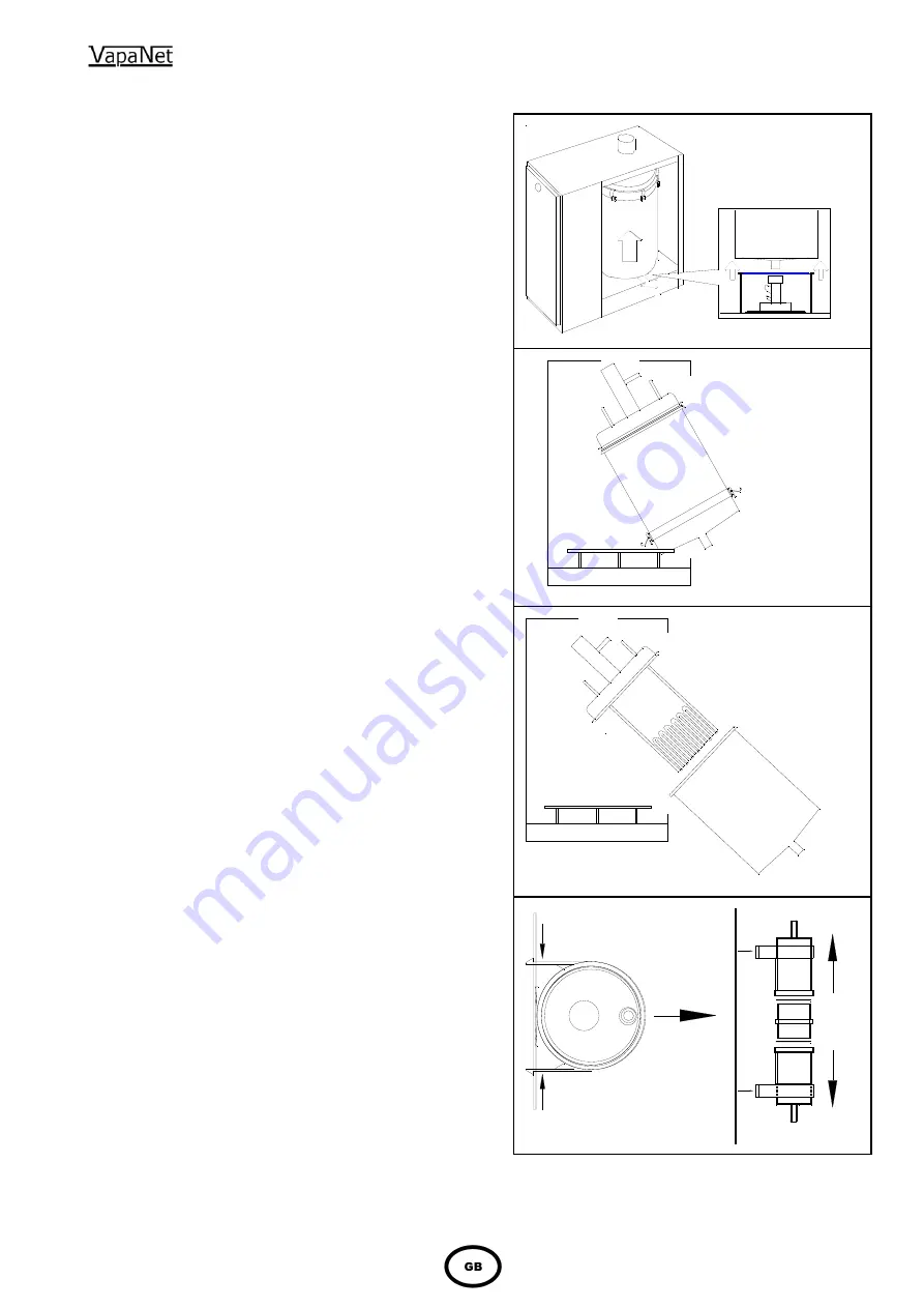
2.1.1 Cylinder
Inspection.
(See figs 1 - 4)
1
ENSURE THAT THE UNIT IS ISOLATED FROM
THE POWER SUPPLY. Then remove the power
supply plug from the fixed socket.
2
Lift cylinder until the bottom (ø 22 mm) spigot is
clear of the feed/drain manifold.
NB it may be
necessary to remove the steam hose from the
cylinder, (top) steam outlet spigot, to achieve this.
3
Bring the base of the cylinder forward then allow the
cylinder to rest on the cylinder support ring, then
remove the cylinder.
4
Undo the securing latches, remove the clamping
ring and lower cylinder casing.
5
Empty any loose scale from the lower casing, and
clean as necessary.
6
Inspect the elements, for excessive scale build-up
or damage, and clean/ replace as required -
Should it be necessary to replace elements,
ensure that they are replaced with the same type
and power. Please also ensure that the integral
cables are re-connected exactly as the original.
When disconnecting an element, please note
the points of disconnection.
7
With the lower cylinder casing removed, and access
to the float chamber improved remove the float
chamber by unclipping it from the back panel and
open the housing by removing the two plastic clips
(use a screwdriver to lever these off) & pulling it
apart (see fig 4).
8
Inspect the float switches, and clean/de-scale as
necessary. A build up of scale can prevent correct
operation of the switches, which - in turn - will lead
to operational problems with the unit.
9
Re-assemble cylinder by repeating the above steps
in reverse. To ensure that the cylinder seals
correctly, ensure that the first four clamps that are
tightened, are those at the four quadrants. I.e.
tighten one clamp then tighten the one
diametrically opposite. Then tighten one at
approximately 90
o
to them and then tighten the
one diametrically opposite. Finally, tighten any
remaining clamps.
Fig 1
Fig 2
Fig 3
Fig 4


