


12
2.0
Start-Up / Operation
2.0.1
Start-up check list
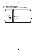
a)
Water supply and Drain Connections
:
These should be connected as indicated
under Plumbing and in accordance with the
relevant local regulations. An isolation valve
should be adjacent to the unit. The
connecting
metal
plumbing
must
be
grounded close to the unit.
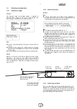
b)
Steam Line:
This must be connected
according to the installation instructions with
adequate slope and support.
c)
Power supply:
Wiring to the Vapanet unit
should be by a qualified electrician and
comply with the relevant regulations using
appropriately sized cable and cable glands,
with disconnect and fuses to suit the
maximum fuse rating of the unit at the supply
Voltage. The disconnect/fuses should be
adjacent to the unit or within easy reach and
readily accessible.
d)
Control Connections:
Ensure the control
signal and security circuit are correctly
connected
according
to
the
relevant
instructions/diagrams.
e)
VAPANET
24v
Control
Circuit
Transformer:
The
standard
24V
transformer used in the units has primary
winding for 200V, 220/240V, 380V, 415V, &
440v 50/60Hz connection derived from the
local electrical supply.
Note: 60Hz connection must be specified
with order as 230V 60Hz pump is required.
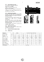
f)
The maximum output & kW rating of the unit
is determined by a Current Set Plug. It is
therefore possible to down rate units to any
output, down to approximately 50% of the full
rated output. (Contact Vapac for further
details)
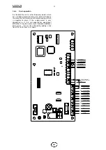
g)
Unit Configuration Plug (U.C.P.) sets the
maximum current level for the unit. It is fitted
directly onto the control P.C.B.
2.0.2
Start-Up Instructions
First check:
a)
That the transformer connection matches
supply Voltage.
b)
That the security circuit is closed for unit
operation.
Close the electrical access panel.
Turn on the water supply to the unit.
Close disconnect/circuit breaker feeding supply to the
unit.
Close the On/Off switch.
2.0.3
Commissioning/Start-Up
Once the Set-Up procedure has been completed, the
unit is available to operate according to the
requirements of the control signal.
When starting with an empty cylinder, the VAPANET
programme switches in the contactor and feeds water
in until the water reaches the electrodes, and current
starts to flow. Thereafter the VAPANET system will
continuously monitor and control the conductivity by
adjusting the amount of water drained and fed into the
cylinder.
With no demand the LE unit’s user LED’s will be off.
When the demand increases and the unit is switched
on the user LED’s will flash green/amber at a rate
depending on the demand input and the actual
current drawn. The actual run current is monitored
and until the actual current has two feeds above 95 %
the LED will flash green/amber when the current is
above 95% for two consecutive feeds the LED’s will
flash red.
2.0.4
Features of VAPANET Electrode
Boiler Unit
The VAPANET system of control is designed to adjust
the function to keep the unit operating in the face of
changing water quality in the cylinder and changing
electrode condition even if, in an adverse operational
circumstance, this results in some reduction in output
while the situation exists.
Foaming protection
In particular, the VAPANET is designed to prevent the
onset of foaming and to introduce corrective drainage
to keep the unit working.
Automatic switch-off
The VAPANET PCB will stop operating in response to
extreme fault conditions identified as:
Drain Fault STOP (no drain function)
Feed Fault STOP (water not reaching cylinder)
In each case, the display will show the STOP
condition and a Help Message, the User LED’s on the
fascia will indicate the condition see table on page 20.
The STOP condition of a VAPANET PCB will be
cleared by switching the unit off and on.
THIS ACTION
SHOULD ONLY BE TAKEN ONCE THE CAUSE OF THE
PROBLEM HAS BEEN ASCERTAINED AND RECTIFIED.
2.1
Service Advice
The water hardness and the humidity demand at site will
determine the effective life of a steam cylinder. Units located
in areas with naturally soft waters will experience the longer
cylinder life, possibly upwards of 12 months in calendar
terms. With hard waters, a more frequent cylinder exchange
must be expected and cylinder exchange 2 or 3 times a year
can be the average situation. The normal scaling up of the
Vapac steam cylinder is outside the Vapac warranty.
2.1.1
Procedure for Cylinder Exchange.
A)
Remove the drain tray assembly from the
unit, as follows:-
1. With the power connected to the unit, manually
drain the unit, by depressing (and holding) the
Run/Off/Drain Switch to the momentary drain
position.
2. Disconnect the Vapac from the incoming
electrical supply by means of the external isolator
(disconnect switch). This should be “locked off” to
prevent accidental operation.
3. Remove the steam section access panel.
4. Remove the plug connection for the float
switches and drain tray condensate pump.
5. Remove the electrode connections.
6. Disconnect the drain pump.
7. Remove the steam distribution assembly by lifting
it clear of the cylinder steam outlet boss. Note it
may be necessary to rotate it as it is raised to get
it high enough to clear the boss.
Содержание VapaNet LFE Series
Страница 19: ...19 3 3 Facia Label symbols 1 ...
Страница 21: ...21 ...


