


I N S T A L L A T I O N
©Vantage, 8/1/2016 / IS-00703-C
Vantage DMX DALI Gateway – MODEL: DMX-DALI-GW
page 5 of 6
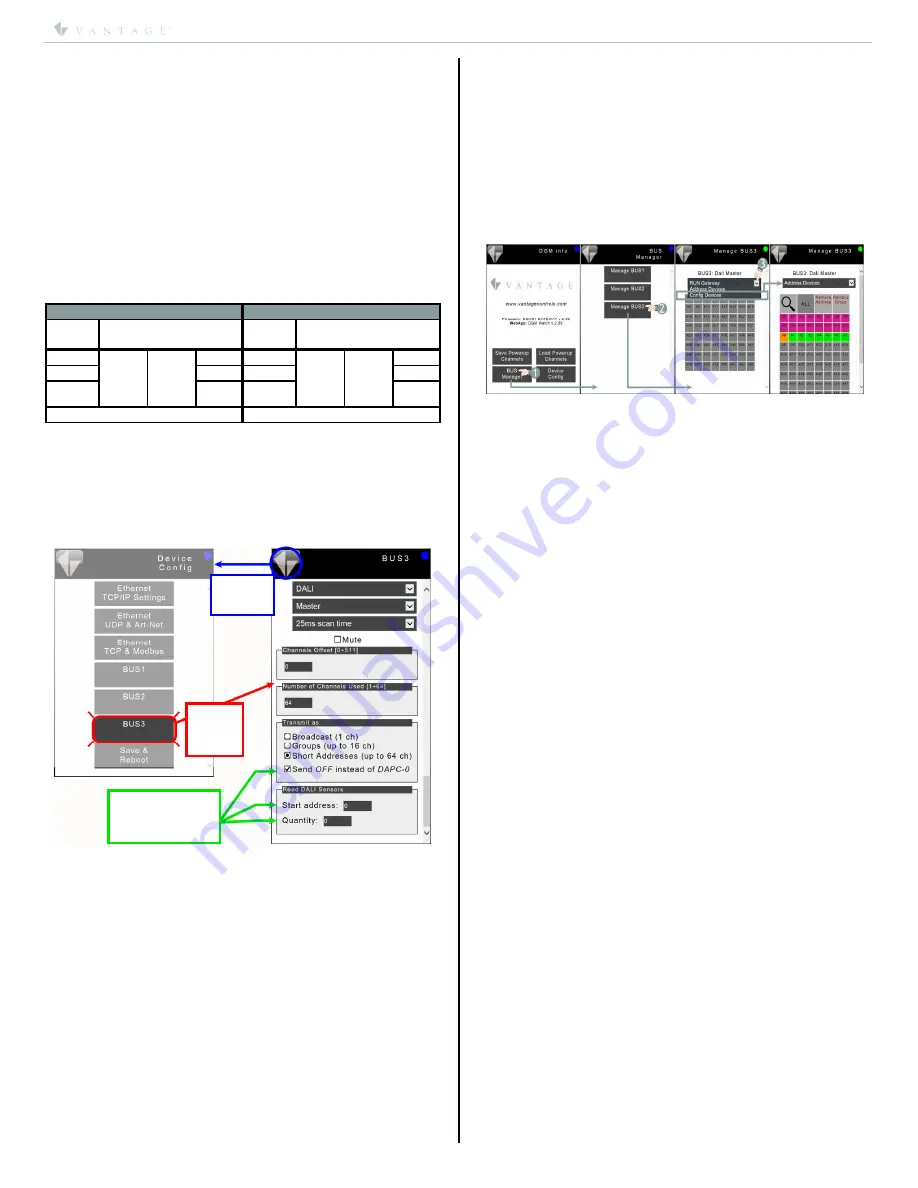
Click To
Return To
Home Screen
Click To
Change
Screen To
DALI Bus 3
Do not use these settings
with the vantage system.
These settings are only
for stand alone applications.
Using the DALI Bus
IMPORTANT NOTE FOR DALI BUS
DALI loads are always commissioned using addresses 0-63.
o
The DDG station automatically adds one (1)* to the
DALI channel making it 1-based and
may
also have an
offset value applied to the channel - the default offset
value is
zero
(0).
Formula: DALI c1 + offset.
*NOTE:
The DDG station automatically adds 1 to the DALI
channel number when receiving data and subtracts 1 from
the channel number when sending data making it match
the DALI 0-based number system.
Typically, the DALI
channel list,
obtained from the DALI
load commissioning person will require adding 1 to each
channel number on said list plus the offset value if an offset
exists.
For example, the DALI list may need changed as follows:
DDG station with Default offset of 0
DDG station with an offset of 50
DALI
Channel
Design Center /
DGM Watch Channel
DALI
Channel
Design Center /
DGM Watch Channel
0 +1
added
by
DDG
+0
offset
value
1 0 +1
added
by
DDG
+50
offset
value
51
1 2
1 52
2 3
2 53
etc. etc.
If the DALI installation has been set up as DALI groups, follow
the steps below to configure the DDG station.
SETTING GROUPS FOR DALI BUS
1.
Type
http://192.168.1.225/config.html
in a browser.
a.
Replace the 192.168.1.225 with the IP address saved
in the
DMX-DALI-GATEWAY Setup Steps
above.
2.
Click
BUS 3
to open the DALI bus configuration screen.
3.
In the
Transmit as
section click
Groups (up to 16 ch)
.
4.
Return to the home page and select
Save & Reboot
.
5.
With this change made, when DALI channels 1 through 16
are sent from the InFusion Controller, the DDG station will
automatically convert and send the correct command for
groups 1 through 16.
6.
No special considerations need to be made in Design
Center other than the DALI channels are now DALI groups
with a maximum of 16.
NOTE: The options in the green arrow section as indicated in
image above are for standalone installs. These settings are
available by scrolling down in the DALI bus window.
BUS Manager (Assigning DALI Addresses)
Through the DGM interface, the
BUS Manager
tool is used to
manage settings on BUS 3 / DALI BUS. This tool allows DALI
loads to be addressed / commissioned through the DDG
station. The tool also allows global settings for the DALI BUS
as covered in the previous column.
BUS Manager Steps (DALI)
In the steps below please allow time for the DALI devices to
reconfigure when addresses are changed and etc.
IMPORTANT: When making any changes using the BUS
Manager tool for Address Devices and /or Config Devices,
always change the drop-down menu back to RUN Gateway to
return the gateway to operational status.
1.
Initial System Setup
a.
Assuming the system consists of new DALI devices -
i.
Navigate to the
Address Devices
page following
the steps in image below.
ii.
Click the magnifying glass to search for devices.
iii.
This assigns a unique short address (starting at
A0) to each DALI device discovered on the bus
and should show up as green boxes in the
address table.
iv.
Each load discovered may be identified by
clicking on any green address box to toggle the
load.
v.
Drag and drop any green box on any other
gray
address box to reassign the address of that load.
Use care to only drag the load to a
gray
square,
indicating an available address, to avoid address
conflicts.
vi.
When using the
Address Devices
tool for
previously addressed DALI loads, the process is
basically the same. Exceptions for handling any
address conflicts are outlined below.
2.
Adding New Loads To An Existing System
a.
All existing loads in the system will show up as green
boxes in the address table.
b.
Clicking the magnifying glass search button will
discover
newly connected
DALI devices and assign
them the lowest available address. Once these loads
have been given an address, they will show up as
green boxes and can now be reassigned to a different
address by following the same process listed above.
c.
There is still the potential for address conflicts if the
newly connected device was previously assigned an
address.
3.
Replacing Loads In An Existing System
a.
When a load goes bad and/or loses communication
with the Bus, the load will no longer appear as a
Green Box in the table. Depending on the position of
the previously addressed load in relation to the other
existing addressed loads, this will leave a
hole
in the
table. When a new device is connected to the bus,
and discovered by clicking the search button, it
should be assigned the lowest available address -
which should correspond to the hole that was left
empty by the broken device. Obviously, if the existing
loads on the system aren’t addressed sequentially, it
is possible that the newly added device will show up
at a different address. Drag the new load to the
address left vacant by the broken device.
4.
Address Conflicts
a.
Anytime there are multiple loads assigned to the
same address, all loads assigned to that address will
be controlled together, and any attempt to drag the
green address box to another address will simply
reassign all the loads to the same new address.


