


www.fmiproducts.com
125784-01D
16
INSTALLATION
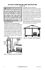
Continued
PRESSURE TESTING HEATER GAS
CONNECTIONS
1. Open equipment shutoff valve (see Figure
14, page 15).
2. Open main gas valve located on or near
gas meter for natural gas or open propane/
LP supply tank valve.
3. Make sure control knob of heater is in the
OFF position.
4. Check all joints from equipment shutoff valve
to gas valve (see Figure 15 or 16, page 15).
Apply noncorrosive leak detection fluid to all
joints. Bubbles forming show a leak.
5. Correct all leaks at once.
6. Light heater (see
Operation
, page 28 de
-
pending on your model). Check all other
internal joints for leaks.
7. Turn off heater (see
To Turn Off Gas to
Appliance
, page 28, depending on your
model).
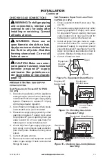
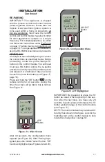
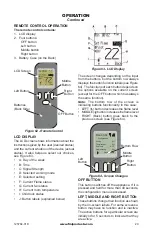
POWER SUPPLY AND BATTERY
INSTALLATION
It is helpful to have a flashlight so you can
see the connections as described below. Lo-
cate the battery power supply. It is the black
box with the red and black wires. Locate the
control module (see Figure 17). Connect the
battery power supply to the control module
by plugging the battery power supply to the
mating receptacle on the control module. The
receptacle is located on the side of the black
control module next to the word “SUPPLY”
which is molded in the control module’s black
housing (see Figure 17). Be certain to push
the plug fully into the receptacle. Install bat-
teries in the battery power supply and hand
held remote control.
Figure 17 - Control Module
S1 Button
Connect Battery Plug Here
Touch Pad Wire Harness
Touch Pad Control
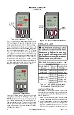
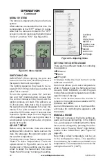
TOUCH PAD INSTALLATION
Locate the touch pad wire harness and the
touch pad control (see Figure 18). They are
shipped from the factory in the clear plastic
bag with your owner’s manual. Connect the
black plastic connectors together as shown
in Figure 19. Connect the remaining end
with the white plastic connector to the control
module in the socket marked TOUCH LED
(see Figure 20).
NOTE:
The touch pad includes a red LED
display light. If the LED remains on, the black
plug is connected upside down. You must
unplug the touch pad control from the touch
pad wire harness, turn over, and reconnect.
Figure 19 - Touch Pad Control Cable
Figure 18 - Touch Pad Wire Harness and
Touch Pad Control
Figure 20 - Connecting end of Touch Pad
Cable