Vanguard 6500 PLUS Скачать руководство пользователя страница 57

Installation 

2-49

Installing Nodes in Modulus Enclosures

Preparing Modulus Enclosures for RFI Suppression

Introduction

To meet FCC requirements, the Modulus 18 and Modulus 21 enclosures require 
special RFI suppression hardware. In the Modulus 18 enclosure, the RFI suppression 
scheme differs depending on whether a TRIM card is installed in the unit.

Modulus 18 with 
TRIM Card

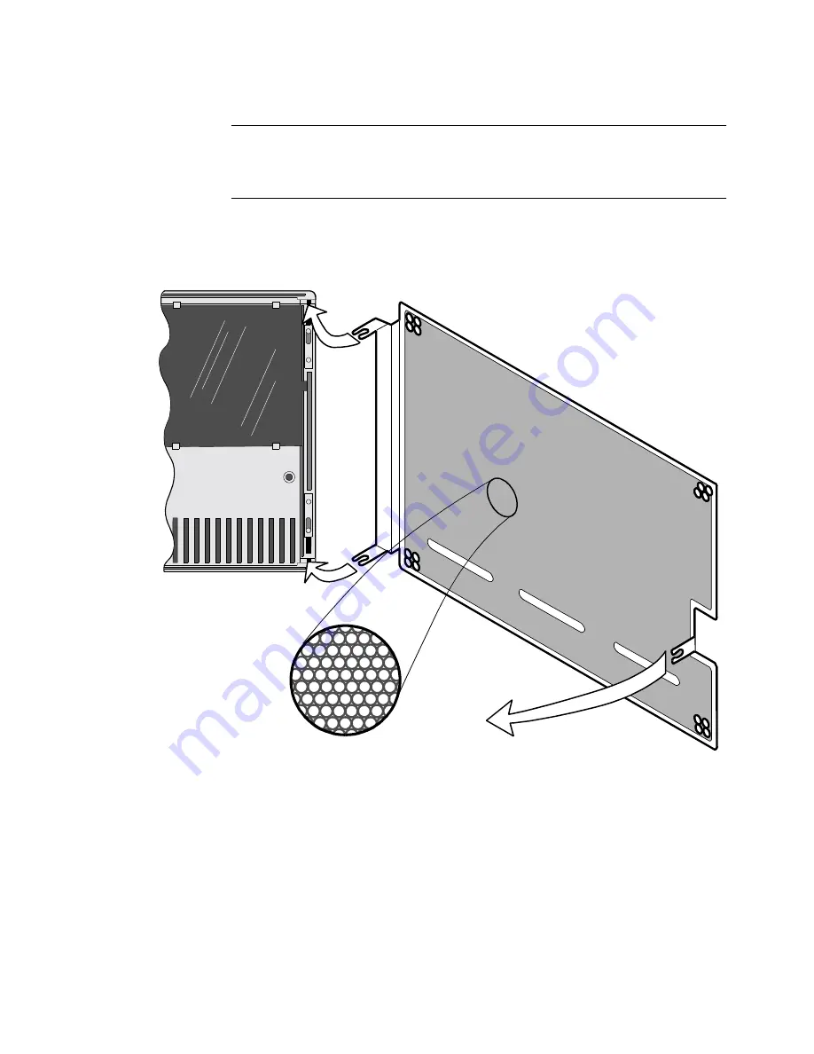
Figure 2-14 shows a Modulus 18 enclosure with a TRIM card. It also shows the 
suppression screen that you need to install. 

Figure 2-14. RFI Suppression Screen (Modulus 18 - with TRIM Card)

Honeycomb Mesh RFI Screen

Modulus 18 Door

(Inside View)

Snap tab into spring rods
on top and bottom of door.

Snap
remaining tab
to door.

Содержание 6500 PLUS

Страница 1: ...Vanguard Managed Solutions Vanguard 6500PLUS Installation Manual...

Страница 2: ...cured for use by the Department of Defense the following legend applies Restricted Rights Legend Use duplication or disclosure by the Government is subject to restrictions as set forth in subparagraph...

Страница 3: ...quipment is operated in a commercial environment This equipment generates uses and can radiate radio frequency energy and if not installed and used in accordance with the instruction manual may cause...

Страница 4: ......

Страница 5: ...f Multi Processor Node 2 30 Adding a Secondary 6500PLUS Processor with FLASH 2 32 Installing Replacing Processor Cards 2 35 Requirements for Installing a TRIM Card 2 36 Installing and Connecting a TRI...

Страница 6: ...stalling Software Options 2 77 Accessing Node Serial Number from Node Statistics 2 78 Enabling A Software Access Key 2 80 Installing New Software Options in an Existing Network 2 81 Enhanced LAN Optio...

Страница 7: ...This Manual The following table describes the contents of this manual Downloading Software For operating software download procedures refer to 6500PLUSDownloading Procedures This Chapter Describes Cha...

Страница 8: ...urnit des informations qui si elles ne sont pas observ es peuvent se traduire par des dommages pour le logiciel le mat riel ou les donn es Vorsicht Ein Vorsichtshinweis macht Sie darauf aufmerksam da...

Страница 9: ...w Introduction The 6500PLUS is a family of networking devices that can operate in private networks or over public data networks A 6500PLUS node can have from 6 to 54 ports with terminal port speeds of...

Страница 10: ...calls into the node s Control Terminal Port CTP a software module that acts as the logical control terminal port In addition configurations can be saved and restored when a PC with Kermit protocol is...

Страница 11: ...ce Module TRIM card Processor Cards The 6500PLUS processor cards provide the basic functions of a 6500PLUS node and can be modified as required The 6500PLUS processor cards are necessary to run 6500PL...

Страница 12: ...hich must be a processor card A standalone unit supports up to six X 25 or terminal ports depending on the type of processor card installed Figure 1 1 6500PLUS Standalone Enclosure Modulus Enclosure T...

Страница 13: ...olds nine 6500PLUS product cards and supports up to 54 ports It is designed to be installed in an industry standard 19 inch rack Note Two processor cards are needed to support 54 ports Backplanes To a...

Страница 14: ...card you can Use only one 6505PLUS processor card in each node Increase the maximum number of ports to 24 by adding up to three asynchronous I O AIO cards Have only two network ports per node these mu...

Страница 15: ...6500PLUS node contains only one type of processor card For example a single node may include up to nine 6525PLUS processor cards but it cannot contain a mix of 6525PLUS and 6507PLUS processor cards Th...

Страница 16: ...running and download in progress TEST Red Indicates status and result of test affecting any part of the node Tests can be locally or remotely initiated On Test failed Off Normal condition Flashing Te...

Страница 17: ...LASH memory module can be attached to a processor card to provide software distribution and software download capabilities This optional daughtercard contains up to 3 Mbytes of nonvolatile FLASH memor...

Страница 18: ...ASH module meaning that the card lacks software storage capabilities Optionally you can purchase a FLASH module for a 6500PLUS auxiliary processor card for downloading software The front panel is the...

Страница 19: ...US cards The UIO card provides six asynchronous or synchronous ports You can configure ports as X 25 MUX or PAD ports Optionally you can configure them to operate with synchronous access protocols SDL...

Страница 20: ...T P O R T 1 2 3 4 5 6 T M 1 2 3 4 5 6 P C 68904 P O R T DATA IN Yellow On Data entering port SPACE Off Data entering port MARK TEST Red Indicates status and result of test affecting any part of node T...

Страница 21: ...orage capacity of 1 4 Mbytes MS DOS formatted disks The disk drive is used to download new and optional software to the node The card contains 1 Mbyte of DRAM which can be increased in 2 Mbyte increme...

Страница 22: ...Option Card 6500 NSO TEST P C 68908 MEM1 MEM3 MEM5 TEST Red Indicates status of internal tests On Test failed Off Normal condition Flashing Test in progress MEM Yellow Indicates amount of memory avail...

Страница 23: ...n a Modulus enclosure A single node can support just one TRIM card Modulus 8 and Modulus 9 enclosures can support one node containing a TRIM card Modulus 18 and Modulus 21 enclosures can support a max...

Страница 24: ...6500PLUS processor cards can support the TRIM card A TRIM compatible processor card has a LAN COMPATIBLE marking on the lower front panel Figure 1 3 If your processor card does not have this marking...

Страница 25: ...consists of two hardware modules the Data Interface Module DIM and the External Interface Module EIM DIM The DSU DIM is a small approximately 1 in x 3 5 in circuit card installed as a daughtercard on...

Страница 26: ......

Страница 27: ...de For Modulus 9 21 enclosures see the Modulus 9 and 21 Installation and Operation Guide Warning etc The following special notices apply to all equipment handling procedures in this chapter Be sure a...

Страница 28: ...e in a clean location free from shock vibration and extremes of temperature and humidity The site must meet the physical and environmental requirements listed in Appendix B Specifications Be sure ther...

Страница 29: ...nel lights turn on as described in the Power Up Verification section on page 2 74 After a few minutes the green STATUS light comes on to indicate the node is ready to process calls If this does not oc...

Страница 30: ...ting on its cover Figure 2 4 and locate the six locking tab slots three on each side There are four locking clips two in the front and two in the back in the slots 3 Using a small pair of pliers remov...

Страница 31: ...alling Standalone Units Door Removal Figure 2 3 shows how to remove the door on the standalone enclosure Figure 2 3 Remove the Standalone Enclosure Door Front Door To remove door separate mounting tab...

Страница 32: ...Installing Standalone Units Enclosure Resting on Cover Figure 2 4 shows the bottom of the standalone enclosure Figure 2 4 Bottom of Standalone Enclosure Locking Tab Slots Locking Tab Slots Plastic Loc...

Страница 33: ...Installation 2 25 Installing Standalone Units Locking Tabs Figure 2 5 shows how to release the tabs Figure 2 5 Using Screwdriver on Locking Tabs...

Страница 34: ...sure that the clear plastic insulator is in place under the card When pressing the replacement card into the backplane connector use direct force Wiggling the card may damage it The card s tabs and th...

Страница 35: ...requires alignment of the backplane and the locking tabs Be sure that the cables are not pinched between the enclosure and metal parts When all elements are correctly aligned the locking tabs snap int...

Страница 36: ...g up Modulus 8 18 enclosures attaching product backplanes inserting cards and attaching front and rear filler panels to the enclosures refer to the Modulus Planning and Installation Guide For general...

Страница 37: ...ions with both processors working Processor 1 handles the I O interrupts from its own six on board ports The processor card in the lowest numbered slot is the master In Figure 2 7 Processor 1 is the m...

Страница 38: ...cessor configuration must operate on the same revision of software If they do not have the same software revision remove the software from the failed processor card and exchange it with the software o...

Страница 39: ...Installation 2 31 Installing Nodes in Modulus Enclosures...

Страница 40: ...re when you want to Maintain the current software revision Upgrade with software from the new 6500PLUS processor card In both cases the FLASH Enable Option is required These situations apply to the 65...

Страница 41: ...node Making the software in the new processor s FLASH the operating revision of software in the node Retaining the node s configuration and options Step Action 1 At the control terminal port use the...

Страница 42: ...lot 3 Exchange the ID Module and CMEM chips between the master 6500PLUS processor card and the new 6500PLUS processor card See the Replacing ID Modules section on page 2 63 and Replacing the CMEM Chip...

Страница 43: ...handling and grounding precautions including the use of an anti static grounding strap whenever you handle a card Replacement Procedure After inserting or removing a card press the Reset button on th...

Страница 44: ...marking see your VanguardMS sales representative to order a LAN capable processor card In multiple CPU configurations only the processor card supporting the TRIM card needs to be LAN compatible Produc...

Страница 45: ...s two Modulus slots The TRIM filler panel for Modulus 8 18 nests is two slots wide as shown in Figure 2 8 Figure 2 8 TRIM Card Rear Filler Panel for Modulus 8 18 Enclosures 65xx 18 Port Backplane Shie...

Страница 46: ...ach a TRIM card only to the processor card in the lowest numbered slot of a backplane this is the master processor in a multi processor node There must be two empty slots beside the backplane next to...

Страница 47: ...8 7 10 11 12 13 14 15 16 17 18 Slots TRIM Card Filler Panel 6500 Node 18 Port Backplane Processor Card TRIM Card Front Modulus 8 18 Filler Panel 1 2 3 4 5 6 9 8 7 10 11 12 13 14 15 16 17 18 Slots TRIM...

Страница 48: ...isting node be sure the enclosure has room for it as described above To make space you may need to rearrange cards and backplanes which requires a node shutdown first A processor card with attached TR...

Страница 49: ...ists of a one slot wide product card plugged into a two slot wide backplane then one slot can be saved when installing a TRIM The modem product should be installed to the left of the TRIM card To inst...

Страница 50: ...Left most Position of Modulus 21 Enclosure Modulus 21 Slot Nest Top View Processor Card Note TRIM card installed in left most position in Modulus 21 The TRIM card requires two slots for its backplane...

Страница 51: ...cards depends on the sizes of the enclosures and backplanes you choose TRIM Card Front Modulus 9 21 Filler Panels 1 2 3 4 5 6 9 8 7 10 11 12 13 14 15 16 17 18 Slots 9 21Trim Card Filler Panel 6500 No...

Страница 52: ...2 44 Installation Installing Nodes in Modulus Enclosures...

Страница 53: ...odulus space considerations described in previous sections 2 Attach the TRIM rear filler panel to the enclosure If you are installing the TRIM card in a Modulus 8 18 enclosure use a Phillips head scre...

Страница 54: ...the slots filled by the TRIM card 4 The TRIM card supports only one LAN connection Use either the DB9 or the RJ45 connector to make the LAN connection but do not attach cables to both If your LAN cabl...

Страница 55: ...ing the Cables The LAN port is Port 55 regardless of how many active X 25 PAD or MUX ports are in your node To configure the LAN port and for information about LAN statistics see the Vanguard ONS Basi...

Страница 56: ...plied by a PROM chip on the TRIM card The BIA is used as the LAN port MAC address if the Port MAC Address parameter in the Port configuration record is set to a default value of 00 00 00 00 00 00 If y...

Страница 57: ...enclosure the RFI suppression scheme differs depending on whether a TRIM card is installed in the unit Modulus 18 with TRIM Card Figure 2 14 shows a Modulus 18 enclosure with a TRIM card It also show...

Страница 58: ...ave older model 6500 nodes non 6500PLUS nodes installed in Modulus 21 enclosures you must install similar RFI straps in the Modulus 21 enclosure as well Step Action 1 Open the door of the enclosure If...

Страница 59: ...FI suppression straps Figure 2 15 RFI Suppression Straps Modulus 18 No TRIM Card Remove a screw from the left and right power supplies Align the bottom of the strap so it is over the screw hole insert...

Страница 60: ...re installing a TRIM card in a Modulus 21 enclosure add the RFI suppression bar as shown in Figure 2 16 The bar is notched to fit across the inside of the door Figure 2 16 RFI Suppression Bar Modulus...

Страница 61: ...ection After a few minutes the green STATUS light comes on to indicate the node is ready to process calls If this does not occur call your VanguardMS representative 2 Configure the unit through the co...

Страница 62: ...ers on the port interface pins Install single in line memory modules SIMMs Replace a FLASH module Replace the ID Module Replace PROMs Replace the CMEM chip Processor Card Figure 2 17 shows the locatio...

Страница 63: ...nents on the card Caution 6500PLUS cards and their components are sensitive to static discharge which can damage components Use proper handling and grounding precautions including the use of an anti s...

Страница 64: ...emoval Figure 2 18 DIM Removal New DIM Installation If you install a new type of DIM on the 6500PLUS processor card you may need to change the jumpers on the port interface jumper pins Figure 2 19 sho...

Страница 65: ...the jumpers should be placed on the pins for various applications and enclosures Figure 2 19 Jumpers on the Port Interface Pins Port 1 Port 2 V 35 V 36 X 21 for Standalone and Backplanes with 25 Pin D...

Страница 66: ...2 58 Installation Replacing Processor Card Components Jumper Installation Figure 2 20 shows how to install the jumpers Figure 2 20 Installing Jumpers on the Port Interface Pins...

Страница 67: ...ckets U81 and U82 Installation Procedure Follow these steps to install a SIMM Caution 6500PLUS cards and their components are sensitive to static discharge which can damage components Use proper handl...

Страница 68: ...0 Installation Replacing Processor Card Components Example of SIMM Installation Figure 2 21 shows how a SIMM is installed in a slot Figure 2 21 SIMM Installation Insert SIMM into socket at a slight an...

Страница 69: ...1 Remove the card from the nest or enclosure You might have to wiggle the card until the header pins disengage from the socket on the card 2 a Loosen and remove the four screws that hold the FLASH mo...

Страница 70: ...tallation Replacing Processor Card Components Installation Example Figure 2 22 shows an example of a FLASH module installation Figure 2 22 Flash Module Installation FLASH Module Header Pins Card Socke...

Страница 71: ...move the card from the nest or enclosure 2 Locate the ID Module Figure 2 17 and note the location of the notch which is toward the front of the card This will help you orient the new chip 3 Using a st...

Страница 72: ...in Figure 2 22 Note the location of the notch on each chip and using a standard chip puller remove the PROMs This will help you orient the new chips Note Not all four PROM sockets may have PROMs 5 In...

Страница 73: ...the nest or enclosure 2 Locate the CMEM chip Figure 2 17 On the CMEM chip note the location of the dot in the lower left corner which is toward the front of the card This will help you orient the new...

Страница 74: ...DTE position only The DSU option will not operate if the DIM is installed in the DCE position You can install up to two DSUs per platform using both ports 1 and 2 Example of Installing the DSU DIM Fi...

Страница 75: ...troubleshooting the CTP port must be used Network Management is not supported for the Integral DSU option Step Action 1 Install the DSU DIM in the DTE position only see Figure 2 23 The DSU option doe...

Страница 76: ...ation Step Action 1 Refer the Vanguard ONS Basics Protocols Manual T0106 However you do not need to complete these configuration parameters Clock Speed Connection Type Port Control 2 Configure the clo...

Страница 77: ...nd of the connection is available BPV Bipolar Violation This signal is H during normal operation When the signal is L it indicates that some type of bipolar violation was received by the DSU option Th...

Страница 78: ...te Time Menu Diagnostics Path Main 12 1 Local Loopback 2 V 54 Loopback 2 3 V 54 Loopback 3 4 Fatal Error Reports 5 Logged Alarms 6 Startup Diagnostics 7 DSU Internal Loopback 8 DSU Internal and Extern...

Страница 79: ...de Statistics Used to verify that the software is a version which contains the DSU option modifications It also shows if the DSU DIM is recognized by the software Port Statistics Used to verify that d...

Страница 80: ...rvice provide the telephone company with the following information USOC number of the required jack shown below Facility interface codes Service code Regulations Concerning Electromagnetic Radiation T...

Страница 81: ...fferent outlet so that the equipment and receiver are on different circuits If necessary you should consult the dealer or an experienced radio television technician for additional circuits You may fin...

Страница 82: ...ates that the node is ready to process calls You may also see some of the port lights remain on depending on their configuration Checking the Lights If you want to make sure that all the lights are wo...

Страница 83: ...re node you can reboot a node to initiate the power up diagnostics After the power up diagnostics are complete check the Statistics screens to see the results To initiate power up diagnostics press th...

Страница 84: ...eps to default the node using the DFLT switch Step Action 1 Push the DFLT switch to the left and press the RESET button 2 Push the DFLT switch to the right when the STATUS light turns steady on and pr...

Страница 85: ...on only one specific node How to Get a SAK If you purchased the option with the 6500PLUS processor card your VanguardMS sales representative will supply the SAK for the option on that card To purchase...

Страница 86: ...The default password is CR After you enter the password the Main menu appears 3 From the Main menu select Status Statistics 4 Select Node Stat The Node Statistics consists of several screens The 6500P...

Страница 87: ...led Node Statistics Page 3 of 7 Board 1 Board Type CPU Number of ports 6 Status Running Serial 1806280 Memory Configuration EPROM 1 0 MBytes DRAM 1 0 MBytes FLASH 2 0 MBytes Flash Memory Software Used...

Страница 88: ...er the following at the prompt ctp CR You are prompted to enter the password 2 Enter the password The default password is CR After you enter the password the Main menu appears 3 From the Main menu sel...

Страница 89: ...new software options in an existing network and you want to get the serial number for a remote node at a central site Step Action 1 Place a call to the CTP at a remote node 2 Log in to the remote node...

Страница 90: ...ired to enable this feature What It Does for the 6500PLUS The Enhanced LAN Option provides a CSK IP Routing SNMP for the 6500PLUS This CSK enables the full IP Routing capability for SNMP management ac...

Страница 91: ...gnals with X 21 DIMs on the processor card Standalone and Modulus 8 18 enclosures EIA 232 D crossover cable Token Ring LAN STP shielded twisted pair cable pinouts Token Ring LAN UTP unshielded twisted...

Страница 92: ...ERNAL RECEIVE CLOCK or V 54 Loop 3 20 DTR 20 DTR 21 V 54 Loop 2 21 V 54 Loop 2 22 RI TM 22 NC No Connection 24 EXTERNAL TRANS MIT CLOCK 24 EXTERNAL TRANSMIT CLOCK 25 TEST MODE 25 MAKE BUSY Pin assigne...

Страница 93: ...OUND 8 DATA CARRIER DETECT 8 DATA CARRIER DETECT 13 TRANSMIT CLOCK B 13 TRANSMIT CLOCK B 14 TRANSMITTED DATA B 14 TRANSMITTED DATA B 15 TRANSMIT CLOCK A 15 TRANSMIT CLOCK A 16 RECEIVED DATA B 16 RECEI...

Страница 94: ...IGNAL GROUND 7 SIGNAL GROUND 8 I A INDICATION A 8 INDICATION A 13 S B TRANSMIT CLOCK B 13 TRANSMIT CLOCK B 14 T B TRANSMITTED DATA B 14 TRANSMITTED DATA B 15 S A TRANSMIT CLOCK A 15 TRANSMIT CLOCK A 1...

Страница 95: ...D 7 SIGNAL GROUND 8 DATA CARRIER DETECT 8 DATA CARRIER DETECT 13 TRANSMIT CLOCK B 13 TRANSMIT CLOCK B 14 TRANSMITTED DATA B 14 TRANSMITTED DATA B 15 TRANSMIT CLOCK A 15 TRANSMIT CLOCK A 16 RECEIVED DA...

Страница 96: ...A INDICATION A 8 INDICATION A 13 S B TRANSMIT CLOCK B 13 TRANSMIT CLOCK B 14 T B TRANSMITTED DATA B 14 TRANSMITTED DATA B 15 S A TRANSMIT CLOCK A 15 TRANSMIT CLOCK A 16 R B RECEIVED DATA B 16 RECEIVED...

Страница 97: ...5 20 6 22 25 24 17 25 22 16 21 21 16 Pin Function 1 Receive 6 Receive 5 Transmit 9 Transmit NOTE All other pins are reserved and should remain unconnected Pin Function 4 Receive 5 Receive 3 Transmit 6...

Страница 98: ......

Страница 99: ...e Part No 09564 Rev B Physical Characteristics Unit Dimensions 6500 Standalone Enclosure Height 2 75 in 6 99 cm Width 8 54 in 21 69 cm Depth 16 00 in 40 64 cm Weight 5 00 lb 2 3 kg Modulus 8 Height 14...

Страница 100: ...8 lb 21 8 kg Max Number of 6500 Series Product Cards 9 Unit continued Dimensions Standalone Enclosure 100 240 VAC nominal 47 to 63 Hz Modulus 8 100 120 VAC 8 0 A 50 to 60 Hz 220 240 VAC 6 0A 50 to 60...

Страница 101: ...1 4 Modulus Types 1 5 standalone 1 4 External Interface Module EIM 1 17 F Features control terminal support 1 2 FLASH module adding second processor wth 2 32 replacement 2 61 Front panel lights 2 74...

Страница 102: ...lation 2 59 Replacing cards Modulus enclosure 2 35 standalone enclosure 2 22 RFI grounding straps 2 50 RFI suppression bar 2 46 RS reset 2 69 S SAK 2 77 entering 2 80 ID Module 2 77 SIMM installation...

Отзывы: