ATO-
250™ Operating Procedures
8
10.0 Operating Procedures
Before novice operators use the ATO-250 to
measure any resistance, they should review
Figure 5.0, the
Step-by-Step Operating
Procedures
for
the ATO-250. The figure
shows the flowchart of the branching of the
multiple test options. The ATO-250
operation is simple, thus requiring minimal
input. The operator only needs to select
choices from the display menus and
responding to the displayed prompts.
10.1 Precautions
The purpose of the ATO-250 is to measure
non-inductive low resistance devices such as
high-power, circuit-breaker contacts.
WARNING
Do not measure resistance of any
inductive device, which will create an
unsafe, high-voltage spike due to the
collapsing of the magnetic field if the
test current is interrupted by a
detachment of a test lead. Do not
disconnect or touch any test lead
connected to a device being tested
while current is being conducted.
Failure to heed this warning can
result in personal injury and damage
to the ATO-250.
If the resistance of an inductive device
is desired, Vanguard Instruments does
manufacture the WRM, an instrument
designed for that purpose.
10.2 Preparations
a.
Plug the ATO-250 power cable into a
120-volt power outlet. If the unit is setup for
240-volt operation, plug the power cable
into a 240-volt outlet receptacle.
b.
Insert the test-current cable plugs and the
test voltage-sensing cable plugs into the
respective control-panel jacks.
c.
Attach the opposite terminals of the test-
cable clamps to the resistive load that is to
be tested. (See Figure 4.0)
NOTE
It is important that the test clips be securely
attached to the contact bushings, bus bar or
junction terminals to eliminate errors from
contact resistance, due to the possibility that
the test currents can be as high as 250
Amperes.
d.
To turn on the ATO-250’s power, press
“
I
” on the rocker switch. (Item 4 in Figure
1.0)
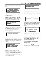
Observe that after the configuration data is
displayed briefly, then the START UP menu
is shown:
11.0 Run Test Procedure
A resistance may be measured by
performing the following step-by-step
sequence. However, if a test is to be fully
documented, the identification data must
also be entered for the equipment that is to
be tested. See Section 12.0 for entering the
identification data. Since the test time and
date will be stored with test record, the clock
and date must be also be correct before any
test is performed.
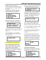
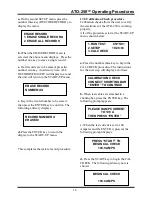
a.
Press the number one key on the START-
UP menu. The CONNECT CABLES prompt
will display:
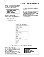
b.
Slowly turn the CURRENT CONTROL
knob until the desired test current is shown.
CONNECT CABLES THEN
ADJUST DRIVE TO
DESIRED CURRENT
(250 A MAX)
1.RUN TEST 05/15/01
2.SETUP 10:28:23
3.CAL CHECK


