background image

AIR N ARC

®

 200 SERIES ALL-IN-ONE POWER SYSTEM

®

SECTION 6: MAINTENANCE

090019-OP_r0

PAGE - 55

6.1  GENERAL INFORMATION

A strict maintenance program is the key to long life for the
Air N Arc 200 Series All-In-One Power System package.
Below is a program that, when adhered to, should keep
the package in top operating condition. Refer to 

Section

6.5, Parts Replacement and Adjustment Procedures

in this section of the manual for detailed descriptions of
specific compressor system components. The following
table lists the main topics in order of appearance for this
section:

6.2  ROUTINE MAINTENANCE 

SCHEDULE

Vanair

®

 Manufacturing, Inc. considers the maintenance

schedule given in 

Section 6.3, Maintenance Schedule

Table

, to be part of the warranty agreement with the

customer. This maintenance regimen must be followed in
order to protect the warranty of the machine package.

Vanair Manufacturing, Inc. especially requires that a
consistent service regimen be established for engine oil
changes, and engine and compressor air filter servicing.
The following schedule is designed so that many of the
other maintenance tasks are completed when the engine
and compressor air filters are serviced, and the engine oil
is changed.

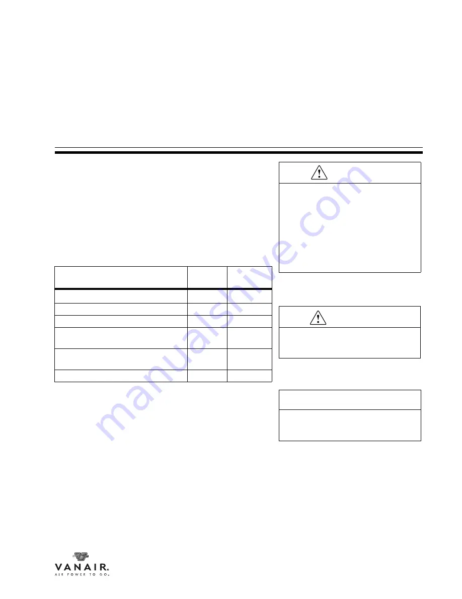
System Component or 

Component Group

Manual 

Section

Location

Routine Maintenance Schedule

6.2

page 55

Maintenance Schedule Table

6.3

page 57

Replacement Parts

6.4

page 64

Parts Replacement and Adjustment 
Procedures

6.5

page 61

Servicing the System Fuses and Cir-
cuit Breakers

6.6

page 96

Storage and Intermittent Use

6.7

page 98

SECTION 6: MAINTENANCE

WARNING

DO NOT remove caps, plugs and/or other 

components when compressor is 

running or pressurized. Stop compressor 

and de-pressurize system prior to 

maintenance of system.

Wear personal protective equipment 

such as gloves, work boots, and eye and 

hearing protection as required for the 

task at hand.

NOTE

Operating the machine package in a 

severe environment may require more 

frequent service intervals.

WARNING

Follow all applicable safety 

recommendations as outlined in 

Section 

1: Safety

 of this manual.

Содержание AIR N ARC RELIANT 250 Series

Страница 1: ...Addendum 090044_r0 to Manual 090019 OP_r0 Effective Date 4 2013 Vanair Manufacturing Inc 10896 West 300 North Michigan City IN 46360 www vanair com NOTE THIS EXCERPT IS THE AIR N ARC 250 ADDENDUM TO T...

Страница 2: ...WELDER OUTPUT 250A high Frequency DC CC DC CV 100 duty Cycle 250 Amps 2 OIL CAPACITY 2 Quarts 3 WELDER MAX AMPERAGE 250 5 4 VARIABLE POWER DIAL ADJUSTS THE WELDER AMPERAGE Range from 30 to 255 AMPS 5...

Страница 3: ...Addendum 090044 AIR N ARC 250 SERIES ALL IN ONE POWER SYSTEM ADDENDUM PAGE III BLANK PAGE...

Страница 4: ...Addendum 090044 PAGE IV ADDENDUM AIR N ARC 250 SERIES ALL IN ONE POWER SYSTEM 1 3 15 7 9 4 11 13 8 5 12 14 8 5 16 10 17 2 9 6 ENGINE AND DRIVE PARTS PA6100021ID_r0...

Страница 5: ...SCREW HEX GR5 3 8 16 x 1 75 829106 175 3 8 WASHER LOCK 1 4 838504 062 5 9 WASHER LOCK 3 8 838506 094 4 10 OIL MOTOR 10W30 2 5 QUART 844300 001 1 11 SHEAVE SERPENTINE 8 GROOVE A15891Z 1 12 SHEAVE 2 GRO...

Страница 6: ...ions Subject to Change Without Prior Notice Vanair Manufacturing Inc 10896 West 300 North Michigan City IN 46360 Phone 219 879 5100 800 526 8817 Service Fax 219 879 5335 Parts Fax 219 879 5340 Sales F...

Страница 7: ...WARRANTY NOTE Use only Genuine Vanair Parts Inspect and replace damaged components before operation Substituting non Vanair components WILL VOID THE COMPRESSOR WARRANTY Vanair Manufacturing Inc 10896...

Страница 8: ...cial industrial users and persons trained and experienced in the use and maintenance of industrial equipment In the event of a warranty claim covered by this Limited Warranty the exclusive remedies sh...

Страница 9: ...NAVIGATION 2 SECTION 1 SAFETY 3 1 1 GENERAL INFORMATION 3 1 2 DANGERS WARNINGS CAUTIONS AND NOTES 3 1 3 INTERNATIONAL SAFETY SYMBOL 4 1 4 ARC WELDING HAZARDS 4 1 4 1 ELECTRICAL SHOCK CAN KILL 4 1 4 2...

Страница 10: ...UMES AND OVERHEATING 12 1 6 3 COMPRESSED AIR CAN CAUSE INJURY 13 1 6 4 TRAPPED AIR PRESSURE AND WHIPPING HOSES CAN CAUSE INJURY 13 1 6 5 HOT METAL FROM AIR ARC CUTTING AND GOUGING CAN CAUSE FIRE OR EX...

Страница 11: ...LOAD TRIP RESET BUTTONS 29 2 5 6 AC VOLTAGE OUTLETS 30 2 5 7 GENERATOR CONTROL ON OFF TOGGLE SWITCH 30 2 5 8 DC CHARGER MODE TOGGLE SWITCH 30 2 5 9 VOLTS AMPS MANUAL ADJUSTMENT DIAL 30 2 5 10 COMPRESS...

Страница 12: ...VOLTAGE MODE USING A SPOOL GUN 48 5 5 OPERATING THE GENERATOR 49 5 6 OPERATING THE AIR COMPRESSOR 49 5 7 OPERATING THE BATTER BOOSTER CHARGER 51 5 7 1 CONNECTION DISCONNECTION SEQUENCE AND OPERATION 5...

Страница 13: ...LT GUARD SHIELD 80 6 5 7 3 RE TENSIONING THE AIR COMPRESSOR DRIVE BELT S 80 6 5 7 4 COMPRESSOR BELT SIZING 81 6 5 7 5 COMPRESSOR BELT LINK DISENGAGEMENT 82 6 5 7 6 COMPRESSOR BELT ASSEMBLY 83 6 5 7 7...

Страница 14: ...MENT PANEL 124 9 6 ENGINE AND DRIVE PARTS 128 9 7 BELT GUARD ASSEMBLY 130 9 8 ELECTRICAL SYSTEM 132 9 9 FUEL TANK ASSEMBLY 136 9 10 CONTROL ASSEMBLY 138 9 11 DECAL AND PLATE LOCATIONS 1 OF 3 140 9 11...

Страница 15: ...aximum short circuit current with consistent amperage regardless of the voltage output Constant Voltage CV Welding Machine This type of welding machine output maintains a relatively stable consistent...

Страница 16: ...circuit is open The voltage is impressed upon the circuit however so that when the circuit is completed the current will flow immediately Plasma Arc Cutting An arc cutting process which severs metal...

Страница 17: ...essure Gauge Reads amount of pressure in the air hose which supplies the tool with air Moisture Separators devices for collecting and removing moisture precipitated from the air or gas during the proc...

Страница 18: ...GLOSSARY AIR N ARC 200 SERIES ALL IN ONE POWER SYSTEM PAGE X 090019 OP_r0 BLANK PAGE...

Страница 19: ...3 Contact the Vanair Service Department by phone 1 219 879 5100 to speak with a Service Technician 4 Vanair Service will troubleshoot the problem based on the information provided by the customer 5 If...

Страница 20: ...S ALL IN ONE POWER SYSTEM PAGE XII 090019 OP_r0 Figure W 1 Machine Serial Number Location 800 526 8817 PSIG 260940 MODEL NUMBER SERIAL NUMBER MAXIMUM PRE SSURE COMPRE SSOR INPUT RPM www vanai r com Fi...

Страница 21: ...uring strives to continuously improve its customer service Please forward any questions comments or suggestions to Vanair Service 219 879 5100 or e mail us service vanair com NOTE The RMA number must...

Страница 22: ...WARRANTY PROCEDURE AIR N ARC 200 SERIES ALL IN ONE POWER SYSTEM PAGE XIV 090019 OP_r0 BLANK PAGE...

Страница 23: ...ble service This unit is weather resistant and able to operate in temperature extremes ranging from 20 F to 110 F see Section 6 7 Extreme Condition Operation The AC generator features a brushless main...

Страница 24: ...e figure the inner columns represent the machine application data in a continuous page by page flow The outer columns are reserved for auxiliary information relating to the specific data put forth in...

Страница 25: ...this manual before operation or performing maintenance actions 1 2 DANGERS WARNINGS CAUTIONS AND NOTES DANGER Identifies actions or conditions which if not avoided will cause death or severe bodily i...

Страница 26: ...and machine internal circuits are also live when power is on In semiautomatic or automatic wire welding the wire wire reel drive roll housing and all metal parts touching the welding wire are electric...

Страница 27: ...y if damaged bare wiring can kill Turn off all equipment when not in use Do not use worn damaged undersized or poorly spliced cables Do not drape cables over your body If earth grounding of the work p...

Страница 28: ...ell ventilated or while wearing an air supplied respirator Always have a trained watch person nearby Welding fumes and gases can displace air and lower the oxygen level causing injury or death Be sure...

Страница 29: ...isted in Safety Standards Wear approved safety glasses with side shields under your helmet Use protective screens or barriers to protect others from flash glare and sparks warn others not to watch the...

Страница 30: ...able as close to the welding area as practical to prevent welding current from traveling long possibly unknown paths and causing electric shock sparks and fire hazards Do not use welder to thaw frozen...

Страница 31: ...or before going near arc welding gouging or spot welding operations Shielding gas cylinders contain gas under high pressure If damaged a cylinder can explode Since gas cylinders are normally part of t...

Страница 32: ...rotective clothing when working on a battery Stop engine before disconnecting or connecting battery cables or servicing battery Do not allow tools to cause sparks when working on a battery Do not use...

Страница 33: ...rom moving parts Reinstall doors panels covers or guards when servicing is finished and before starting engine Before working on generator remove spark plugs or injectors to keep engine from kicking b...

Страница 34: ...exhaust and exhaust pipes way from flammables 1 5 9 EXHAUST SPARKS CAN CAUSE FIRE Use approved engine exhaust spark arrester in required areas see applicable codes 1 6 COMPRESSED AIR HAZARDS 1 6 1 BRE...

Страница 35: ...ng or changing attachments or opening compressor oil drain or oil fill cap 1 6 5 HOT METAL FROM AIR ARC CUTTING AND GOUGING CAN CAUSE FIRE OR EXPLOSION Do not cut or gouge near flammables Watch for fi...

Страница 36: ...nit 1 7 2 OVERHEATING CAN DAMAGE MOTORS Turn off or unplug equipment before starting or stopping engine Do not let low voltage and frequency caused by low engine speed damage electric motors 1 7 3 FLY...

Страница 37: ...ompressor if applicable maintenance and service according to this manual and the engine air compressor if applicable manuals 1 7 8 H F RADIATION CAN CAUSE INTERFERENCE High frequency H F can interfere...

Страница 38: ...l occurs the user must take extra measures such as moving the welding machine using shielded cables using line filters or shielding the work area 1 8 CALIFORNIA PROPOSITION 65 WARNINGS Welding or cutt...

Страница 39: ...0900 web site www cganet com Code for Safety in Welding and Cutting CSA StandardW117 2 from Canadian Standards Association Standards Sales 178 Rexdale Boulevard Rexdale Ontario Canada M9W 1R3 phone 8...

Страница 40: ...ached you may wish to minimize your exposure to electromagnetic fields when welding or cutting To reduce magnetic fields in the workplace use the following procedures 1 Keep cables close together by t...

Страница 41: ...consult the following WARNING DO NOT REMOVE OR COVER ANY SAFETY LABEL Replace any safety label that becomes damaged or illegible WARNING If applicable For machine packages that contain labels to be af...

Страница 42: ...SECTION 2 DESCRIPTION AIR N ARC 200 SERIES ALL IN ONE POWER SYSTEM page 20 090019 OP_r0 C A1 B E F G H J K N P R L A2 M Q A U V W X Y Z T S D Figure 2 1 MAJOR MACHINE COMPONENTS LOCATIONS...

Страница 43: ...VE P COMPRESSOR AIR FILTER Q COMPRESSOR UNIT R OIL SIGHT GLASS S COMPRESSOR OIL DRAIN PORT Plugged T DC GENERATOR U AC GENERATOR V COMPRESSOR PULLEY FLYWHEEL W COMPRESSOR BELT x 2 Adjacent X GENERATOR...

Страница 44: ...n a harsh industrial environment With proper maintenance it should provide years of reliable service The air compressor is constantly in operation when the machine is on Therefore it provides a consta...

Страница 45: ...ation and provides maximum particulate protection Deep Finned Cylinders and Heads ensure cool vibration free operation and long life Cast Iron High Tensile Strength Rods with replaceable rod bearings...

Страница 46: ...essure drops to the preset load valve setting the ball closes venting the compressor unloading device to atmosphere Since the compressor operation is constant when the machine is on the system is alwa...

Страница 47: ...oil filter while also offering re borable and replaceable cylinders grindable crankshaft replaceable valve guides and seats and heavy duty engine bearings The engine is preset to a fixed speed For in...

Страница 48: ...on the instrument panel The fuel level gauge receives its level signal from the fuel sender that is located in the fuel tank The fuel system also contains a fuel filter 2 4 AC GENERATOR See Figure 2 7...

Страница 49: ...toggle switch and DC charger welder toggle switch welder DC charge WARNING DO NOT rely on breakers for overload protection These breakers are temperature and time dependant and cannot be relied upon...

Страница 50: ...L ON OFF SWITCH 2 5 7 C DC CHARGER WELDER TOGGLE SWITCH 2 5 2 K DC CHARGER 12V 24V TOGGLE SWITCH 2 5 8 D FUEL GAUGE 2 5 3 L VOLTS AMPS MANUAL ADJUSTMENT DIAL 2 5 9 E HOUR METER 2 5 3 M COMPRESSOR AIR...

Страница 51: ...mount of fuel and the hour meter records the total accumulated hours that the package is operated The hour meter can be used to assist in scheduled maintenance planning 2 5 4 ENGINE CONTROL ON OFF STA...

Страница 52: ...MODE TOGGLE SWITCH The three position DC charger mode toggle switch lets the operator choose the type of charge needed from 12V center default 12V boost or 24V boost options This is a momentary switc...

Страница 53: ...F to 110 F 29 to 43 C Consult Section 5 8 Extreme Condition Operation I For in depth specifications and requirements regarding the Kohler 25 EFI engine refer to the Engine Operator s Manual II Ethano...

Страница 54: ...7 16 14 24 17 50 35 60 45 70 55 76 61 7 16 20 34 26 55 40 70 50 80 60 85 68 1 2 13 38 31 75 55 95 70 110 80 113 90 1 2 20 52 42 90 65 100 80 120 90 126 100 9 16 12 52 42 110 80 135 100 150 110 163 13...

Страница 55: ...Load Hi RPM 3660 10 Engine Idle RPM 2000 10 Air Cut in Pressure 150 10 Air Cut out Pressure 175 10 AC Generator Hz no load 61 1 AC Generator 240 Plug 243 3 AC Generator 120 Plug 122 2 AC Generator 120...

Страница 56: ...SECTION 3 SPECIFICATIONS AIR N ARC 200 SERIES ALL IN ONE POWER SYSTEM PAGE 34 090019 OP_r0 BLANK PAGE...

Страница 57: ...ecifications for dimensional requirements Section 4 5 Part 1 and Part 2 for measurements and the following instructions System Component or Part Group Task Manual Section Location Machine Package Prep...

Страница 58: ...cts are shielded or grommeted and that there are no excessively sharp bends in the trunk line Ensure the trunk line does not come in contact with exhaust parts 4 4 MACHINE PACKAGE MOUNTING When determ...

Страница 59: ...G PATTERN WITHOUT SPACER _ Figure 4 2 Remote Panel Mounting Pattern with and without Spacer 10 5 5 0 0 5 10 5 7 5 0 5 A B KEY DESCRIPTION KEY DESCRIPTION A MOUNTING NUT 1 2 x 4 D MOUNTING BOLT 1 2 x 4...

Страница 60: ...itiated check that the fuel pump is energized Wait 3 5 seconds for the fuel pump to prime the fuel system The unit will start more quickly if the fuel pump is manually pre energized to prime the fuel...

Страница 61: ...4 63 49 86 26 49 10 38 8 56 23 79 1 75 R 25 25 A C CIRCUIT BREAKERS OIL FILL ENGINE DIPSTICK ENGINE OIL FILL PORT COMPRESSOR OIL DRAIN HOSE ENGINE OIL ENGINE FUSES BATTERY UNDER HOOD ELECTRICAL FUSES...

Страница 62: ...PTIONAL SPACER REMOTE PANEL WITHOUT SPACER 1 32 10 50 13 13 3 13 5 00 0 44 4X 4 15 5 58 P N A16738P 2 88 7 50 1 31 10 50 13 13 4X 5 16 18UNC SERVICE PORT 2X 1 2 NPT AIR 16 50 4 28 5 16 23 18 15 57 9 1...

Страница 63: ...tart up 5 2 1 page 43 Engine Shutdown 5 2 2 page 44 Engine Throttle Control Functions 5 3 page 45 Operating the Welder 5 4 page 45 Welder Operating Procedure 5 4 1 page 46 CC Constant Current Mode 5 4...

Страница 64: ...TCH K DC CHARGER 12V 24V TOGGLE SWITCH D FUEL GAUGE L VOLTS AMPS MANUAL ADJUSTMENT DIAL E HOUR METER M AIR PRESSURE GAUGE F ENGINE CONTROL ON OFF START SWITCH N BATTERY CABLE RECEPTACLE G CIRCUIT BREA...

Страница 65: ...ce Engine may run at full speed until pressure builds up in the tank Operating the Generator 5 5 page 49 Operating the Air Compressor 5 6 page 49 Operating the Battery Boost Charger 5 7 page 51 Connec...

Страница 66: ...start up session if some of the machine conditions were left in working mode s or had auxiliary power draws left intact such as a tool receptacle left plugged into the generator etc To prepare the mac...

Страница 67: ...gine speed relates to the demand s of the machine system s output functions 5 4 OPERATING THE WELDER Consult Figure 5 3 The variable power dial adjusts the welder amperage 30 to 205 amps or voltage 15...

Страница 68: ...ngine See Section 5 2 Engine Start up and Shutdown Procedure TABLE 5A ENGINE THROTTLE CONTROL FUNCTION CONDITIONSI Air Pressure Generator Switch Welder Switch Engine Speed Condition Result Tank Pressu...

Страница 69: ...trode Using E6010 for an example The E indicates Electrode because some welding rods are not electrodes The 60 in 6010 indicates the tensile strength in psi 60 000 lbs The last two digits indicate pos...

Страница 70: ...monly referred to as Wire Welding MIG welding or Gas Metal Arc Welding GMAW 1 With the engine shut off insert the twist lock connection of the ground clamp into the negative welder connection port on...

Страница 71: ...the white reset buttons on the generator panel to reset the breakers Figure 5 4 5 6 OPERATING THE AIR COMPRESSOR The air compressor on the Air N Arc 200 Power System is a continuous run compressor Th...

Страница 72: ...on consult Section 2 2 4 Pilot Valve and Section A 8 Pressure System Control Function Sequences When purchasing air tools or planning a project the rated capacity of the compressor 24 CFM up to 175 ps...

Страница 73: ...that the welder DC charger switch and any other engine control switch is in the OFF position System Operation Group Manual Section Location Operating the Battery Boost Charger 5 7 page 51 Connection D...

Страница 74: ...When operating in extreme hot or cold conditions extra attention should be given to any indications that could lead to a serious problem Machine review and maintenance check schedules should be more f...

Страница 75: ...y need to be used Check the fuel filter regularly to insure that it contains no water Drain the moisture from the tank when it is warm from extended operation 5 8 2 HIGH TEMPERATURE OPERATION The stan...

Страница 76: ...SECTION 5 OPERATION AIR N ARC 200 SERIES ALL IN ONE POWER SYSTEM PAGE 54 090019 OP_r0 BLANK PAGE...

Страница 77: ...ce regimen be established for engine oil changes and engine and compressor air filter servicing The following schedule is designed so that many of the other maintenance tasks are completed when the en...

Страница 78: ...istance in obtaining routine maintenance or replacement parts consult Section 9 1 Parts Ordering Procedure and Table 9A Recommended Spare Parts List NOTE Follow the prescribed periodic maintenance PM...

Страница 79: ...that concern the compressor drive belts 2 Change engine oil and engine filter Consult Section 6 5 9 2 Checking the Engine Oil and if necessary to change the oil and oil filter refer to Section 6 5 9 3...

Страница 80: ...ion will help to prevent dirt and debris build up which can affect machine operation When cleaning external parts always wait for machine surfaces to cool down before wiping off 14 Inspect serpentine...

Страница 81: ...ce engine air filter Consult Section 6 5 9 1 Engine Air Filter Maintenance on how to change the air filter 22 Check the engine speed Ensure that the engine speed is running at correct interval Adjust...

Страница 82: ...ad valve maintenance procedures 28 Check and tighten all bolts nuts etc if necessary Check all bolt and nut fastenings to assure tightness and or correct torque values where applicable Check more freq...

Страница 83: ...Low Pressure Valve Replacement 6 5 3 2 page 69 High Pressure Valve Maintenance 6 5 3 3 page 70 High Pressure Valve Replacement 6 5 3 4 page 71 Compressor Head Valve Assembly Inspection and Maintenance...

Страница 84: ...ing the Generator Serpen tine Drive Belt 6 5 7 9 page 85 Replacing the Generator Serpentine Belt 6 5 7 10 page 87 Draining the Air Tank 6 5 8 page 89 Engine Maintenance 6 5 9 page 89 Engine Air Filter...

Страница 85: ...re being compression can begin DO NOT clean the compressor air filter element Refer to Figure 6 1 and the following procedure 1 With the machine off and the ignition key removed locate the air filter...

Страница 86: ...er end tab of the spring clamp to lock the spring clamp into place 10 Repeat Steps 8 and 9 for the clamp on the other side of the air filter body to secure the filter into place KEY DESCRIPTION KEY DE...

Страница 87: ...enance 6 5 2 page 65 Compressor Oil Change 6 5 2 1 page 65 TOOLS ITEMS NEEDED REPLACEMENT PART S Compressor Oil if necessary ISO68 Non Detergent Oil WARNING Relieve pressure from the compressor system...

Страница 88: ...r federal laws 6 5 3 UNLOADER VALVE MAINTENANCE The unloader valves for low pressure and high pressure are located on the top of the compressor cylinder head as shown in Figure 6 3 These valves are su...

Страница 89: ...and spring K with soap and water 8 Dry the assembly parts 9 Apply a small amount of o ring lubricant to viton o ring J and reset onto the piston shaft H 10 Reassemble the parts in order taking care to...

Страница 90: ...lt Table 6A Bolt Torques for Compressor for proper torque specification 12 Test to confirm that the valve functions freely by depressing the piston with a small screw driver through the top air port T...

Страница 91: ...sist of Upper cover gasket G Unloading piston H Viton o ring J Unloading spring K Unloading cylinder L Lower unloader gasket M Unloading fork N Washer P Bolt Q TOOLS ITEMS NEEDED REPLACEMENT PART S He...

Страница 92: ...e coat the threads with pipe sealant 10 Replace the copper valve tubing A into position on the tee B and tighten 11 Dispose of discarded valve assembly within the guidelines of all applicable local re...

Страница 93: ...valve assembly 1 Locate the high pressure unloader valve A NOTE After disassembling the valve if the parts appear to be too worn or damaged order the High Pressure Valve Assembly Replacement Kit no R...

Страница 94: ...ads with pipe sealant 9 Replace the copper valve tubing A into position on the elbow B and tighten 10 Dispose of discarded valve assembly parts within the guidelines of all applicable local regional a...

Страница 95: ...PPER 21 BEARING FRONT REAR 34 FRONT OIL SEAL 9 VALVE SEAT GASKET 22 REAR COVER GASKET 35 OIL LEVEL GAUGE GAUGE COVER 10 VALVE PLATE 23 REAR COVER 36 GAUGE COVER SEAL 11 VALVE PLATE SPRING 24 COPPER WA...

Страница 96: ...oosen and remove socket head bolts to separate the upper and lower valve seats This will expose the valve springs and valve plates TOOLS ITEMS NEEDED REPLACEMENT PART S Socket Wrench Compressor Gasket...

Страница 97: ...in position on lower valve plate 6 Place upper valve seat with valve springs and plates tied in position on top of lower valve seat with new valve eat gasket in place between the two seats 7 Start cen...

Страница 98: ...ant running compressors 8 Assemble and tighten discharge tubing 9 Check oil level in crankcase 10 Close and tighten valve or the connections used to relieve air pressure from system 11 Reconnect batte...

Страница 99: ...th the machine off loosen the locknut C and adjust the pressure adjustment nut clockwise in to raise the cut in cut out pressure and counter clockwise out to lower the cut in cut out pressure Using th...

Страница 100: ...mpressor And Or Generator Drive Belts 6 5 7 page 78 Accessing the Drive Belts Removing the Belt Guard Shield 6 5 7 1 page 79 Replacing the Belt Guard Shield 6 5 7 2 page 80 Re Tensioning the Air Compr...

Страница 101: ...ect the battery ground cable TOOLS ITEMS NEEDED REPLACEMENT PART S Large Phillips Head Screw Driver or Drill Bit Drill Not Applicable KEY DESCRIPTION KEY DESCRIPTION A TRUSS HEAD SCREW x 10 C COMPRESS...

Страница 102: ...entry into the Maintenance and Service Log found in Appendix B 6 5 7 3 RE TENSIONING THE AIR COMPRESSOR DRIVE BELT S The poly link v belts used for the compressor drive do not require a separate tens...

Страница 103: ...n C and D 1 Wrap new belt as shown in Figure 6 12 and pull it tight around the pulleys To determine the length overlap the last two holes of one end of the belt with two tabs of the other end matching...

Страница 104: ...ressor Drive Belt No DR270814 2 KEY DESCRIPTION KEY DESCRIPTION A COMPRESSOR PULLEY D OUTER SIDE OF BELT TRACK Arrows printed on links point in the same direction as compres sor pulley direction of ro...

Страница 105: ...D in the direction indicated NOTE Inset E shows how the pressure applied from both thumbs causes the tab to rotate toward the slot position KEY DESCRIPTION KEY DESCRIPTION A Rotate tab B1 90 so that t...

Страница 106: ...4 through 6 5 7 6 to size and assemble the belt 2 The belt should be linked as a completed loop prior to setting it onto the pulley tracks Run belt around the proper belt groove on the engine pulley t...

Страница 107: ...ard must be removed to access the drive belt The Air N Arc 200 Series All In One Power System utilizes a single serpentine v belt to drive the generator system Consult Section 6 5 7 1 Accessing the Dr...

Страница 108: ...e plate Consult Table 6B Measuring Belt Deflection for the proper tension measurement 4 Once a position is achieved that accounts for a satisfactory tension in the belt torque the bolt C to 12 ft lbs...

Страница 109: ...sening the tensioner plate bolt item C in Figure 6 17 and pivoting the generator idler sheave item A in Figure 6 17 to its maximum position the generator belt will be loose enough to remove from the g...

Страница 110: ...tinued from there 4 When the belt has been situated onto each track groove on the drive pulleys and the idler the tension will need to be reset via the position of the idler sheave B and checked To re...

Страница 111: ...operation manual maintenance personnel should also refer to the Engine Operator s Manual when addressing any engine issues on the Air N Arc 200 Series All In One Power System Refer to Figure 6 19 for...

Страница 112: ...ters to have on hand consult Section 6 7 Storage and Intermittent Use TOOLS NEEDED REPLACEMENT PART S Clean Cloth Air Filter Replacement Element No 262722 NOTE DO NOT clean the air filter element KEY...

Страница 113: ...the rubber seal E on the air filter stud H Replace if the seal is worn damaged or questionable 7 Reinstall the components in reverse order of removal 6 5 9 2 CHECKING THE ENGINE OIL Refer to Figure 6...

Страница 114: ...d be within TOOLS NEEDED REPLACEMENT PART S Clean Cloth Engine OilI if necessary Funnel to add oil if necessary I Engine may need additional amount of oil if low Consult Engine Operator s Manual for o...

Страница 115: ...the engine clean the area around the dipstick A remove the dipstick 2 Remove the oil drain plug F and let the oil drain into a receptacle container such as an automotive oil pan Allow ample time for...

Страница 116: ...dipstick see G1 in Figure 6 21 Recheck oil level before adding more oil Refer to Section 6 5 9 2 Checking the Engine Oil 10 Reinstall the oil fill cap and dipstick securely 11 Test run the engine to c...

Страница 117: ...ic procedure 6 5 9 5 ENGINE COOLER MAINTENANCE Refer to Figure 6 23 Periodically as per Section 6 3 IMPORTANT Failure to use the proper replacement filters can result in engine damage and void the war...

Страница 118: ...ft of the battery per Figure 6 25 The fuse holder is situated via a groove C on the mounting side of the TOOLS ITEMS NEEDED REPLACEMENT PART S FIG KEY Fuse Removal Tool recommended or Pliers 40 Amp Au...

Страница 119: ...at local vendor carriers such as automobile supply stores hardware stores etc KEY DESCRIPTION KEY DESCRIPTION A CANOPY Generator s and Battery Housing E RELAYS B CIRCUIT BREAKERS E1 AC GENERATOR C FA...

Страница 120: ...ys treat the fuel with a fuel stabilizer Check all belts and hoses for signs of deterioration such as visible surface cracks stiffness or discoloration 6 7 2 LONG TERM STORAGE Disconnect the battery c...

Страница 121: ...e Troubleshooting Guide Section 7 3 may not cover all possible situations Be aware that additional troubleshooting information may be found in other sources such as the Engine Operator s Man ual Shoul...

Страница 122: ...Consult the Engine Operator s Manual for additional information Continued on next page I Do not attempt to service or replace major engine components or any items that require special timing or adjust...

Страница 123: ...on 6 5 9 1 Air Filter Maintenance Clean or replace as necessary Defective oil pressure switch Check continuity and replace Kohler Oil Sentry Protection switch if necessary refer to Engine Operator s M...

Страница 124: ...place Blown system fuse Check system fuse replace if necessary Refer to Section 6 6 Servicing the System Fuses and Circuit Breakers Broken or faulty wiring Check harness connections and wiring conditi...

Страница 125: ...precleaner are clean and all components are properly secured Clean or replace as necessary Refer to Engine Operator s Manual Restricted cooling air in or out Clean engine intake grill refer to Section...

Страница 126: ...necessary refer to the Engine Operator s Manual Fuel filter s and or fuel lines partly plugged Replace fuel filter or lines Refer to Section 6 5 9 4 Replacing the In line Fuel Filters and the Engine O...

Страница 127: ...ressure Worn valve plate Repair or replace valve plate Valve springs have lost their temper Replace valve springs Dirt on the valve plate Remove and clean it Leaks from safety valve Repair or replace...

Страница 128: ...intenance to clean or rebuild replace Pressure relief valve not operating properly Replace if necessary Leak in air system Inspect air system for leaks Faulty throttle solenoid Check throttle solenoid...

Страница 129: ...tters use a loom cut ting tool or a clean sharp razor blade Pilot valve out of adjustment or malfunctioning Pressure settings may need to be reset Consult Section 6 5 5 Adjusting the Cut in Cut out Pr...

Страница 130: ...refer to Section 6 5 1 Compressor Air Filter Incorrect engine speed Reduce load Refer to Section 6 5 6 Pilot valve stuck open Check valve clean or replace if necessary Excess amount of oil in air dis...

Страница 131: ...or faulty wiring Check wiring Loose secure faulty replace Lights do not turn off Battery charge low Flip AC generator switch to bring engine to high rpm and charge battery AC GENERATOR No AC generator...

Страница 132: ...SECTION 7 TROUBLESHOOTING AIR IN ARC 200 SERIES ALL IN ONE POWER SYSTEM PAGE 110 090019 OP_r0 BLANK PAGE...

Страница 133: ...oblems that may arise while operating the All In One Power System within its intended use The flow schematic and wiring diagram should be used together when identifying any potential prob lems They ar...

Страница 134: ...SECTION 8 DIAGRAMS AIR N ARC 200 SERIES ALL IN ONE POWER SYSTEM PAGE 112 090019 OP_r0 8 2 WIRING DIAGRAM AIR N ARC 200 SERIES ID270712 S1_r0...

Страница 135: ...AIR N ARC 200 SERIES ALL IN ONE POWER SYSTEM SECTION 8 DIAGRAMS 090019 OP_r0 PAGE 113 8 3 WIRING DIAGRAM SWITCHES LIGHTS ID270712 S2_ r0...

Страница 136: ...T 1 6 CO67609 VALVE PILOT VALVE 150 175 PSI 1 5 CO62609 VALVE POP OFF VALVE 70 PSI 1 4 CO59774 VALVE CHECK VALVE 3 4 FNPT 1 3 A18096P TANK 30 GAL 1 2 264232 VALVE RELIEF 200 PSI 1 4 NPT MALE 1 1 26081...

Страница 137: ...from the Bill of Lading for the machine pack age or from the compressor unit serial number plate See Figure 9 1 for location of machine package serial plate Consult Table 9A Recommended Spare Parts Li...

Страница 138: ...5A 2 Figure 6 26 B 16 270501 Relay 40 Amp 3 Figure 6 26 E E1 E2 E3 17 CO62617 Breaker Circuit 20A 2 9 5 28 18 RC46552 Valve Kit Compressor Unloader Low Pressure 1 Figure 6 4 C 19 RC21654 Valve Kit Com...

Страница 139: ...AIR N ARC 200 SERIES ALL IN ONE POWER SYSTEM SECTION 9 ILLUSTRATED PARTS LIST 090019 OP_r0 PAGE 117 NOTES...

Страница 140: ...SECTION 9 ILLUSTRATED PARTS LIST AIR N ARC 200 SERIES ALL IN ONE POWER SYSTEM PAGE 118 090019 OP_r0 9 2 AIR N ARC 200 SYSTEMS ASSEMBLIES 6130020ID_r0A...

Страница 141: ...ARD ASSEMBLY 1 9 7 8 ID FRAME ASSEMBLY SKID MOUNT 1 9 4 9 ID ENGINE AND DRIVE PARTS 1 9 6 10 ID ELECTRICAL SYSTEM REMOTE 1 9 8 11 ID CONTROL ASSEMBLY SKID 1 9 10 12 ID INSTRUMENT PANEL 1 9 5 13 ID FUE...

Страница 142: ...SECTION 9 ILLUSTRATED PARTS LIST AIR N ARC 200 SERIES ALL IN ONE POWER SYSTEM PAGE 120 090019 OP_r0 9 3 COMPRESSOR AND PARTS ASSEMBLY PA35509_r0...

Страница 143: ...VALVE POP OFF VALVE 70 PSI CO62609 1 3 DECAL COMPRESSOR LOGO ROUND DL269684 1 4 TEE BRANCH COMP 1 8MNPT x 1 4 COMP 90 DEG FI46707 1 5 ELBOW COMP 1 8MNPT x 1 4 COMP 90 DEG FI64915 1 6 ADAPTER 90 DEG E...

Страница 144: ...SECTION 9 ILLUSTRATED PARTS LIST AIR N ARC 200 SERIES ALL IN ONE POWER SYSTEM PAGE 122 090019 OP_r0 9 4 FRAME PA6030022ID_r1...

Страница 145: ...ITEM DESCRIPTION PART NUMBER QTY 1 SCREW SER WASH 3 8 16 x 1 829706 100 8 2 PLATFORM 200 A1270312 2 3 MOUNT SKID A16581P 4 4 GROMMET BLACK RUBBER 1 75 ID PR33078 1 5 GROMMET BLACK RUBBER 2 25 ID PR52...

Страница 146: ...SECTION 9 ILLUSTRATED PARTS LIST AIR N ARC 200 SERIES ALL IN ONE POWER SYSTEM PAGE 124 090019 OP_r0 AA 9 5 INSTRUMENT PANEL PA6040022ID_r0...

Страница 147: ...H 5 16 18 x 0 75 829705 075 2 14 WASHER FLAT 1 4 838204 071 2 15 WASHER LOCK 1 4 838504 062 8 16 ELBOW 37FL 90M 08 x 1 2 860208 050 1 17 FACEPLATE CONTROL PANEL A1269483 1 18 PANEL CONTROL BACK A12694...

Страница 148: ...SECTION 9 ILLUSTRATED PARTS LIST AIR N ARC 200 SERIES ALL IN ONE POWER SYSTEM PAGE 126 090019 OP_r0 9 5 INSTRUMENT PANEL CONTINUED PA6040022ID_r0 AA...

Страница 149: ...HARNESS WELD CABLE JUMPER EP270171 1 42 HARNESS A C PANEL TO MACHINE EP270230 1 43 HARNESS WIRE INST PNL EP270780 1 44 SCREW PHILLIPS PAN HEAD 10 32 x 1 2 LG SS FA33542 7 45 PIPE BRASS BULKHEAD 1 2 N...

Страница 150: ...SECTION 9 ILLUSTRATED PARTS LIST AIR N ARC 200 SERIES ALL IN ONE POWER SYSTEM PAGE 128 090019 OP_r0 9 6 ENGINE AND DRIVE PARTS PA6100017ID_r1...

Страница 151: ...EX GR5 3 8 16 x 1 50 829106 150 1 6 CAPSCREW HEX GR5 3 8 16 x 1 75 829106 175 3 7 WASHER LOCK 1 4 838504 062 5 8 WASHER LOCK 3 8 838506 094 4 9 OIL MOTOR 10W30 2 5 QT 844300 001 1 10 SHEAVE SERPENTINE...

Страница 152: ...SECTION 9 ILLUSTRATED PARTS LIST AIR N ARC 200 SERIES ALL IN ONE POWER SYSTEM PAGE 130 090019 OP_r0 9 7 BELT GUARD ASSEMBLY PA6030021ID_r0...

Страница 153: ...9107 100 2 6 CAPSCREW HEX GR5 1 2 13 x 2 25 829108 225 1 7 SCREW SER WASH 3 8 16 x 1 829706 100 14 8 WASHER FLAT 1 2 838208 112 1 9 WASHER LOCK 3 8 838506 094 1 10 WASHER LOCK 7 16 838507 109 2 11 SHI...

Страница 154: ...SECTION 9 ILLUSTRATED PARTS LIST AIR N ARC 200 SERIES ALL IN ONE POWER SYSTEM PAGE 132 090019 OP_r0 9 8 ELECTRICAL SYSTEM PA6120053ID_r0...

Страница 155: ...5 700 2 11 SCREW SER WASH 5 16 18 x 0 75 829705 075 10 12 SCREW SER WASH 5 16 18 x 1 829705 100 6 13 SCREW SER WASH 5 16 18 x 1 25 829705 125 2 14 WASHER FLAT 5 16 838205 071 4 15 WASHER FLAT 1 2 8382...

Страница 156: ...SECTION 9 ILLUSTRATED PARTS LIST AIR N ARC 200 SERIES ALL IN ONE POWER SYSTEM PAGE 134 090019 OP_r0 9 8 ELECTRICAL SYSTEM CONTINUED PA6120053ID_r0...

Страница 157: ...P41345 1 31 BATTERY CABLE NEGATIVE EP59646 1 32 HARNESS REMOTE A C MACHINE EP82587 1 33 SCREW PHILLIPS PAN HEAD 10 32 x 1 2 LG SS FA33542 4 34 NUT LOCK M6 x 1 0 PITCH FA55272 4 35 GENERATOR AC W OUT R...

Страница 158: ...SECTION 9 ILLUSTRATED PARTS LIST AIR N ARC 200 SERIES ALL IN ONE POWER SYSTEM PAGE 136 090019 OP_r0 9 9 FUEL TANK ASSEMBLY OA032767ID_r3 9 10 1 4 5 2 6 3 8 12 8 11...

Страница 159: ...FUEL VENT 1 2 NPT 270956 1 4 PLUG PIPE 1 4 807800 010 1 5 FUEL TANK 11 GAL A1270787 1 6 SENDER UNIT FUEL LEVEL 14 LG CO85672 1 7 HARNESS FUEL SENDER EXTENSION LONG EP270788 2 1 8 CLAMP HOSE T BOLT ST...

Страница 160: ...SECTION 9 ILLUSTRATED PARTS LIST AIR N ARC 200 SERIES ALL IN ONE POWER SYSTEM PAGE 138 090019 OP_r0 9 10 CONTROL ASSEMBLY PA6120060ID_r0...

Страница 161: ...ON 261309 1 3I ELBOW 90 DEG PUSH ON 1 4T x 1 4P 261310 2 4II CONNECTOR 1 4P x 1 4T 261317 1 5 VALVE PILOT VALVE 150 175 PSI CO67609 1 6 TEE MALE STREET 1 8 x 1 8 x 1 8 FI31152 1 7 PIPE BRASS BULKHEAD...

Страница 162: ...ark plug lead before servicing WARNING Do not operate without fan guard in place WARNING Do not use air from this compressor for breathing purposes or processing consumables except in full compliance...

Страница 163: ...PARTS I 1 3 DECAL FAN GUARD I 1 4 DECAL V BELT LINK INFORMATION I 1 5 DECAL DO NOT BREATHE COMPRESSOR AIR I 1 6 DECAL SULFURIC ACID BATTERIES I 1 7 DECAL HOT PARTS I 1 8 WARNING CARBON MONOXIDE I 1 I...

Страница 164: ...t remove caps plugs or other components when compressor is running or pressurized Stop compressor and relieve all internal pressure before doing so WARNING Connect air hoses in full compliance with fe...

Страница 165: ...E FUEL I 1 6II DECAL GASOLINE ONLY I 1 7II DECAL DO NOT USE E 85 DL270183 1 I This decal is included with decal sheet no 263453 II If fuel fill related decals are not mounted on the machine as in the...

Страница 166: ...ALL IN ONE POWER SYSTEM PAGE 144 090019 OP_r0 800 526 8817 PSIG 260940 MODEL NUMBER SERIAL NUMBER MAXIMUM PRE SSURE COMPRE SSOR INPUT RPM www vanair com COMPRESSOR FLUID DRAIN 2 3 A 4 5 1 AIR TANK DR...

Страница 167: ...COMPRESSOR FLUID DRAIN I 1 4 DECAL PERFORMANCE BADGE AIR N ARC 200 DL269665 1 5 DECAL COMPRESSOR LOGO DL269684 1 A Air tank outlet valve per customer installation Decal should be placed near outlet va...

Страница 168: ...SECTION 9 ILLUSTRATED PARTS LIST AIR N ARC 200 SERIES ALL IN ONE POWER SYSTEM PAGE 146 090019 OP_r0 BLANK PAGE...

Страница 169: ...NDUCTION MOTOR CAPACITOR MOTOR SPLIT PHASE MOTOR 1 6 275 400 600 850 1200 1 4 400 500 850 1050 1700 1 3 450 600 950 1350 1950 1 2 600 750 1300 1800 2600 3 4 850 1000 1900 2600 X 1 1000 1250 2300 3000...

Страница 170: ...feet 50 100 feet 100 150 f 2 240 480 22 20 18 3 360 720 22 18 16 4 480 960 20 16 16 5 600 1200 18 16 14 6 720 1440 18 16 14 8 960 1920 16 14 12 10 1200 2400 16 12 12 12 1440 2880 16 12 10 14 1680 366...

Страница 171: ...nt portable 1300 Heater portable liquid fuel 50 000 btu 675 225 100 000 btu 1260 420 150 000 btu 1875 625 Impact wrench 1 2 750 600 3 4 900 750 1 1400 1200 Milk cooler 1800 1100 Mixer 3 cubic feet 230...

Страница 172: ...er 18 SCFM Impact Screw Driver 28 8 SCFM Speed Saw 36 43 2 SCFM Body Saw 57 6 SCFM Jig Saw 43 2 SCFM 16 Gauge Nibbler 28 8 SCFM Cut off Tool 28 8 SCFM 150 mm Air Hammer 28 8 SCFM 190 mm Air Hammer 30...

Страница 173: ...T This kit factory install extends cold weather temperature operation range from 0 F to 40 F 18 to 40 C 032793 1 4 BATTERY BOOST CABLES These cables are 25 feet in length with quik connect ends MA2699...

Страница 174: ...0 cable with electrode holder and connector 330 amp MA269814 25 1 14 WELD LEAD 50 feet in length 1 0 cable with electrode holder and connector 330 amp MA269814 50 1 15 WELD LEAD 25 feet in length 1 0...

Страница 175: ...ius should be provided to avoid collapsing of line and restriction of flow 3 Exceeding minimum bend radius will greatly reduce hose assembly life 4 Use elbows or other adapters as necessary to elimina...

Страница 176: ...any welding procedure the operator must be aware of general safety practices and particularly those pertaining to welding as found in Section 1 4 of this manual TABLE A PROCESS CONTACTOR SWITCH SETTI...

Страница 177: ...Manual switch ON PRESSURE SWITCH N C 10 PSI Engergizes pilot when tank pressure signal is 10 psi PILOT VALVE Manual switch OFF COMPRESSOR BUILDING PRESSURE COMPRESSOR OFF COMPRESSOR VENTING T O ATMOSP...

Страница 178: ...APPENDIX A ADDITIONAL INFORMATION AIR N ARC 200 ALL IN ONE POWER SYSTEM PAGE 156 090019 OP_r0 BLANK PAGE...

Страница 179: ...ntenance and particularly Section 6 3 Maintenance Schedule Table For procedure on ordering parts consult Section 9 Parts Ordering Procedure Table 9A Recommended Spare Parts List and Appendix A Section...

Страница 180: ...OG Date of Purchase BREAK IN PERIOD SERVICE POINTS Date Completed 100 HOURS OR ONE YEAR SERVICE POINTS Dates Completed Parts Replaced 200 HOURS SERVICE POINTS Dates Completed Parts Replaced OTHER SERV...

Страница 181: ...OG Date of Purchase BREAK IN PERIOD SERVICE POINTS Date Completed 100 HOURS OR ONE YEAR SERVICE POINTS Dates Completed Parts Replaced 200 HOURS SERVICE POINTS Dates Completed Parts Replaced OTHER SERV...

Страница 182: ...APPENDIX B MAINTENANCE SERVICE LOG AIR IN ARC 200 ALL IN ONE POWER SYSTEM PAGE 160 090019 OP_r0 BLANK PAGE...

Страница 183: ...BLANK PAGE...

Страница 184: ...Change Without Prior Notice 050605 050605 001 050567 050595 Vanair Manufacturing Inc 10896 West 300 North Michigan City IN 46360 Phone 219 879 5100 800 526 8817 Service Fax 219 879 5335 Parts Fax 219...

Отзывы: