SECTION 5: MAINTENANCE
AIR N ARC
®
I
-
300 SERIES ALL-IN-ONE POWER SYSTEM
®
PAGE - 46
090045-OP_r1
service life of the compressor system.
However, you may find that over time they
become loose and need to be tightened. The
proper tension can be determined by using a
tension tester to measure the deflection from
a given force.
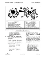
5.4.3.1 RE-TENSIONING THE AIR
COMPRESSOR SERPENTINE
DRIVE BELT
Consult
Figure 5-3
, and the following
procedure.
1. With the machine off and the ignition
key removed, open and remove the
front panel.
2. Loosen the four tensioner plate bolts
[
A
] mounting the tensioner plate [
C
] to
the compressor only enough to allow
tensioner plate to rotate/slide along
the grooves in the plate while still in
position (
DO NOT
remove).
This allows the idler sheave [
B
] to
change position, causing the belt to
be loosened or tightened.
3. Use a 1/2” drive torque wrench
applied to the square tensioning hole
[
D
] to manually rotate the plate/idler
about the loosened, but anchored,
mounting bolt. Apply torque of 40 ft-
lbs.
4. Once a position is achieved that
accounts for a satisfactory tension in
the belt, torque the four (4) tensioner
plate bolts [
A
] to 12 ft-lbs to secure the
tensioner into position.
5.4.3.2 REPLACING THE AIR
COMPRESSOR SERPENTINE
DRIVE BELT
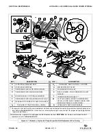
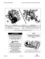
To replace the air compressor serpentine
belt consult
Figures 5-4
and
5-5
, and the
following procedure:
With the machine off and the ignition key
removed, open and remove the access
panel.
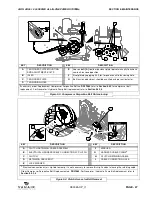
BELT ACCESS AT CLUTCH (
Figure 5-4
)
1. Release the electrical connection wire
[
B
] fastened at the front of the clutch
plate [
C
]. Note that this wire is also
secured at the harness cable clamp [
G
]
.
2. Locate the clutch retaining cable ([
H
]
in
Figure 5-4
) secured to the floor of
the machine near the clutch apparatus
of the engine.
NOTE
It is not necessary to remove the zip tie
securing the clamp to the wire.
Figure 5-2: Pressure Switch Location
B
1
A
B
C
D
B
2
KEY
DESCRIPTION
A
PRESSURE SWITCH
B
COMPRESSOR CUT-IN PRESSURE
ADJUSTMENT SCREW
B
1
TYPE “A” SWITCH SCREW LOCATION
B
2
TYPE “B” SWITCH SCREW LOCATION
C
BATTERY (reference)
D
DC WELDER GENERATOR
(reference)

