


AW
AY
BA
07
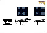
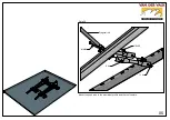
Front view
Fro
nt v
iew
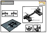
A
Step 1
Take the end clamp out of it's
slot for an easier assembly.
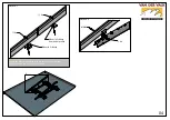
A
Step 2
Step 3
The end clamp can only be turned clockwise,
so make sure the end clamp is placed the right
way.
Step 4
Put the end clamp in the right
slot to continue the assembly.
pa
ne
l h
ei
gh
t
Step 5
8
Nm
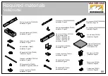
Содержание ValkDouble
Страница 1: ...Version 01 December 2021 Installation manual ValkDouble...
Страница 28: ...09 Mount cable clamp on the panel...


